


English
Operation manual
21
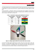
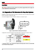
Figure 21 shows a diagram of voltage regulator ARE6076 connection as an example.
Figure 21 - Voltage regulator ARE6076
The voltage regulator type is identified by the terminal contacts and based on the information set
out in Appendices 1, 2. In the example given, terminals IG, S, FR(M) do not identify the type of the
voltage regulator. Terminal L identifies it as a Lamp type.
Then we refer to Appendix 1 to determine which clips (connectors) of the diagnostic cable must
be connected to the voltage regulator. The connection diagram of voltage regulator ARE6076 is
shown in both Table 3 and Figure 22.
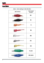
Table 3 – Connection of voltage regulator ARE6076 to the tester
Voltage regulator
terminal
Tester output
terminal
Color marking of
cable
IG
IG
red
L
D+
grey
S
S
orange
FR(M)
FR
white
B+
B+
red
F2
green
F
F1
green
Ps
ST1
blue
GND
B-
black
Summary of Contents for MS016
Page 2: ......
Page 105: ...MS016 105 ...
Page 106: ...MS016 106 ...
Page 108: ...MS016 108 ...
Page 109: ...MS016 109 ...
Page 110: ...MS016 110 ...
Page 111: ...MS016 111 ...
Page 112: ...MS016 112 ...
Page 113: ...MS016 113 ...
Page 114: ...MS016 114 ...
Page 115: ...NOTES 115 ...
Page 116: ......


