


INSTALLATION INSTRUCTIONS 7
M S D
• W W W . M S D P E R F O R M A N C E . C O M • ( 9 1 5 ) 8 5 7 - 5 2 0 0 • F A X ( 9 1 5 ) 8 5 7 - 3 3 4 4
Figure 5 Timing Retard vs Time From Activation
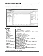
MONITORS
MONITOR
DESCRIPTION
Engine RPM*
Engine speed (RPM) received from PN7730
Ignition Timing*
Ignition timing referenced to Top Dead Center (TDC) received from
PN7730
Timing Retard*
Total retard currently applied
Temperature
External temperature sensor reading
Time From Activation*
Time from release of the activation source
Ignition Voltage
Voltage supplied on the ignition wire
1-Red Input
Input 1 (Red) status (ON or OFF)
1-Red Output Duty Cycle
Output 1 (Red) duty cycle. When selected as a digital output,
ON is 100% and OFF is 0%
2-Orange Input
Input 2 (Orange) status (ON or OFF)
2-Orange Output Duty Cycle Output 2 (Orange) duty cycle. When selected as a digital output,
ON is 100% and OFF is 0%
3-Pink Input
Input 3 (Pink) status (ON or OFF)
3-Pink Output Duty Cycle
Output 3 (Pink) duty cycle. When selected as a digital output,
ON is 100% and OFF is 0%
4-Yellow Input
Input 4 (Yellow) status (ON or OFF)
4-Yellow Output Duty Cycle
Output 4 (Yellow) duty cycle. When selected as a digital output,
ON is 100% and OFF is 0%
* This monitor is only available in Power Grid mode
sensor while going down the track. When connected to the Power Grid, the Power Module
sends the enabled channels over the CAN bus to be recorded by the Power Grid. The channels
will be recorded at a rate of 5 samples per second.