


INSTALLATION INSTRUCTIONS 3
M S D
• W W W . M S D P E R F O R M A N C E . C O M • ( 9 1 5 ) 8 5 7 - 5 2 0 0 • F A X ( 9 1 5 ) 8 5 7 - 3 3 4 4
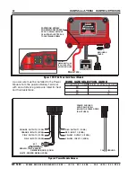
MOUNTING
The Power Module must be mounted in a sturdy, dry location and away from extreme heat. The Power
Module should be mounted using the included rubber mounts to limit excessive vibration. The unit
should not be immersed or subjected to direct spray from a power washer.
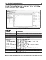
MSDVIEW
The MSDView software allows editing of the Output Settings, Timing and Data Acquisition tabs, as
well as turning features on/off and setting up and retrieving data logs.
The following information provides a brief explanation of each function or feature.
While using the software, you can mouse over each item for a brief on-screen explanation. When the
system controller is con nected to a PC via USB, MSDView will automatically recognize it and load
the settings stored in the available modules.
INSTALLATION OF THE MSDVIEW SOFTWARE
1. Insert the installation Flashdrive into available USB port.
2. Locate the ‘autorun.exe’ file on the Flashdrive.
3. Click on “Install MSD View Software”. Click ‘Yes’ when asked ‘Do you want the following program
to make changes to this computer?’.
4. Click ‘Next’ in the ‘Setup - MSD View’ window.
Accept the License Agreement and click ‘Next’.
Choose to accept the desktop icon then click ‘Install’.
Click ‘Finish’ to run application.
5. Connect the Power Module via the USB cable and wait for it to be listed in the product window.
Select the Controller by highlighting the line or checking the box and clicking the ‘View/Hide’ button.
Note:
The software may display a prompt window for the latest updates to be installed.
The latest version of the MSDView Software can be downloaded from www.msdperformance.com.
SAVES AND TRANSFERS
Changes to the Power Module via MSDView are made in real time. You can create and save numerous
different setting files to your PC and load them back into the unit for different applications.
The following will go through a general description of the software for the Power Grid Power Module
PN 7764 Controller.
OPERATION
The 7764 Power Grid Power Module is a fully programmable 4-channel solid state relay. The use
of the Power Module eliminates electromechanical relays and fuses. Any of the four outputs can
be configured as a digital output (i.e ON/OFF) or can be configured as a Pulse Width Modulated
output (i.e. PWM) with user-programmable frequencies up to 10 Kilohertz. The solid state switches
are protected from over-current and over-temperature conditions and can handle currents up to 20
Amperes continuously. The user has the ability to program a lower current limit.
Any of the four input wires or the signal from an external temperature sensor can be used to control
any one of the outputs. Moreover, the Power Module can be used in conjunction with the Power Grid
(PN7730) to expand its programmable options. For instance, when connected to the Power Grid, the
outputs can be controlled by the launch wire signal or as a function of engine speed (RPM).
All the programmable features are configured using the MSDView software provided.
The Power Module has two modes of operation: When the CAN bus is functional, it will operate in
POWER-GRID mode. Otherwise it will operate in STAND-ALONE mode.
Note:
The Power Module self detects the mode of operation by the way it is connected in the circuit.
STAND-ALONE
The user can control any of the four outputs independently using any of the four input wires or the