background image

INSTALLATION INSTRUCTIONS 

3

M S D  

•   W W W . M S D P E R F O R M A N C E . C O M   •   ( 9 1 5 )   8 5 5 - 7 1 2 3   •   F A X   ( 9 1 5 )   8 5 7 - 3 3 4 4

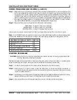
WIRING PROCEDURE (SEE FIGURES 3, 4 AND 5)

Step 1 -  

Make sure that your vehicle is equipped with an ignition ballast resistor (or loom resistance wire) 

in the wire between the ignition switch and the coil (+) terminal. If you find your vehicle is not 

equipped with an ignition ballast resistor, install a Mallory Ignition Ballast Resistor Part No. 700 

in series in the wire from the ignition switch. For optimum performance in systems without a 

HyFire or similar ignition control, use one of Mallory's 3 specially matched coils which eliminates 

the need for a ballast resistor or a resistance wire. These coils are: 29219- Chrome Canister 

Coil, 30450 PROMASTER e Coil and 29450 PROMASTER Classic Coil.

Step 2 - 

There are three wires coming from the distributor wire harness:


RED WIRE:  Connect to the coil (+) terminal.


GREEN WIRE:  Connect to the coil (–) terminal.


BROWN WIRE:  Connect to engine block ground.

Clean away any grease, oil and paint from the mounting surface before the connection is made.

Note:

 If a HYFIRE® Electronic Ignition Control or any other aftermarket ignition control is being used, 

connect the distributor wire harness according to the instructions supplied with the ignition control.

DISTRIBUTOR TUNE–UP PARTS   PART NO.

DISTRIBUTOR CAP  

202

ROTOR  

303

SHUTTER WHEEL (TWO PIECE)  

338

E-Spark™ MODULE  

6100M

DISTRIBUTOR WIRE HARNESS  

29349

STARTING THE ENGINE

CAUTION: 

Be sure all tools, wires and miscellaneous objects are clear of moving engine parts and 

extreme heat before starting the engine.

Recheck all wires and connections to make sure they are correct. Check and clean, or replace spark 

plugs. If replacing spark plugs, use types recommended by the engine manufacturer.

Step 1 -  

Connect a timing light. Find the area with the best view of the timing marks.

Step 2 -  

Start engine. If it fails to start, rotate the distributor in small increments clockwise or 

counterclockwise until engine starts. Do not exceed more than ten degrees of distributor housing 

rotation in either direction.

Step 3 -  

Set timing as recommended by engine manufacturer, then tighten distributor hold down clamp. 

Make sure timing is still correct. If timing has moved, repeat this procedure.

Step 4 -  

Re-connect the vacuum hose between the vacuum chamber and the carburetor.

Summary of Contents for Mallory E-Spark Conversion 61001M

Page 1: ...tor from the engine if the distributor is easily accessible However removal of the distributor from the engine is recommended GENERAL INFORMATION Ignition Coils The E Spark Ignition System is designed to work with most stock ignition coils and aftermarket high performance ignition coils For optimum performance in systems without a HyFire or similar ignition control use one of Mallory s 3 specially...

Page 2: ...on System will operate without the breaker plate ground wire Step 8 Apply a thin coat of heat sink compound to the bottom of the module Install the module onto the mounting plate with two 6 32 x 3 16 screws See Figure 1 Secure the three module wire to the breaker plate with a cable tie Step 9 Install the grommet in the hole in the distributor hosing where the primary point wire had previously fed ...

Page 3: ... the connection is made Note If a HYFIRE Electronic Ignition Control or any other aftermarket ignition control is being used connect the distributor wire harness according to the instructions supplied with the ignition control DISTRIBUTOR TUNE UP PARTS PART NO DISTRIBUTOR CAP 202 ROTOR 303 SHUTTER WHEEL TWO PIECE 338 E Spark MODULE 6100M DISTRIBUTOR WIRE HARNESS 29349 STARTING THE ENGINE CAUTION B...

Page 4: ...4 INSTALLATION INSTRUCTIONS M S D W W W M S D P E R F O R M A N C E C O M 9 1 5 8 5 5 7 1 2 3 F A X 9 1 5 8 5 7 3 3 4 4 ...

Page 5: ...INSTALLATION INSTRUCTIONS 5 M S D W W W M S D P E R F O R M A N C E C O M 9 1 5 8 5 5 7 1 2 3 F A X 9 1 5 8 5 7 3 3 4 4 ...

Page 6: ...6 INSTALLATION INSTRUCTIONS M S D W W W M S D P E R F O R M A N C E C O M 9 1 5 8 5 5 7 1 2 3 F A X 9 1 5 8 5 7 3 3 4 4 ...

Page 7: ...________________________________________________________________ _________________________________________________________________________________________________________________________ _________________________________________________________________________________________________________________________ ___________________________________________________________________________________________...

Page 8: ...covered by warranty For more information call MSD at 915 855 7123 MSD technicians are available from 7 00 a m to 5 00 p m Monday Friday mountain time M S D W W W M S D P E R F O R M A N C E C O M 9 1 5 8 5 5 7 1 2 3 F A X 9 1 5 8 5 7 3 3 4 4 2015 MSD LLC FRM33306 Created 06 15 TECH NOTES _______________________________________________________________________________________________________________...

Reviews: