


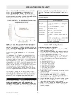


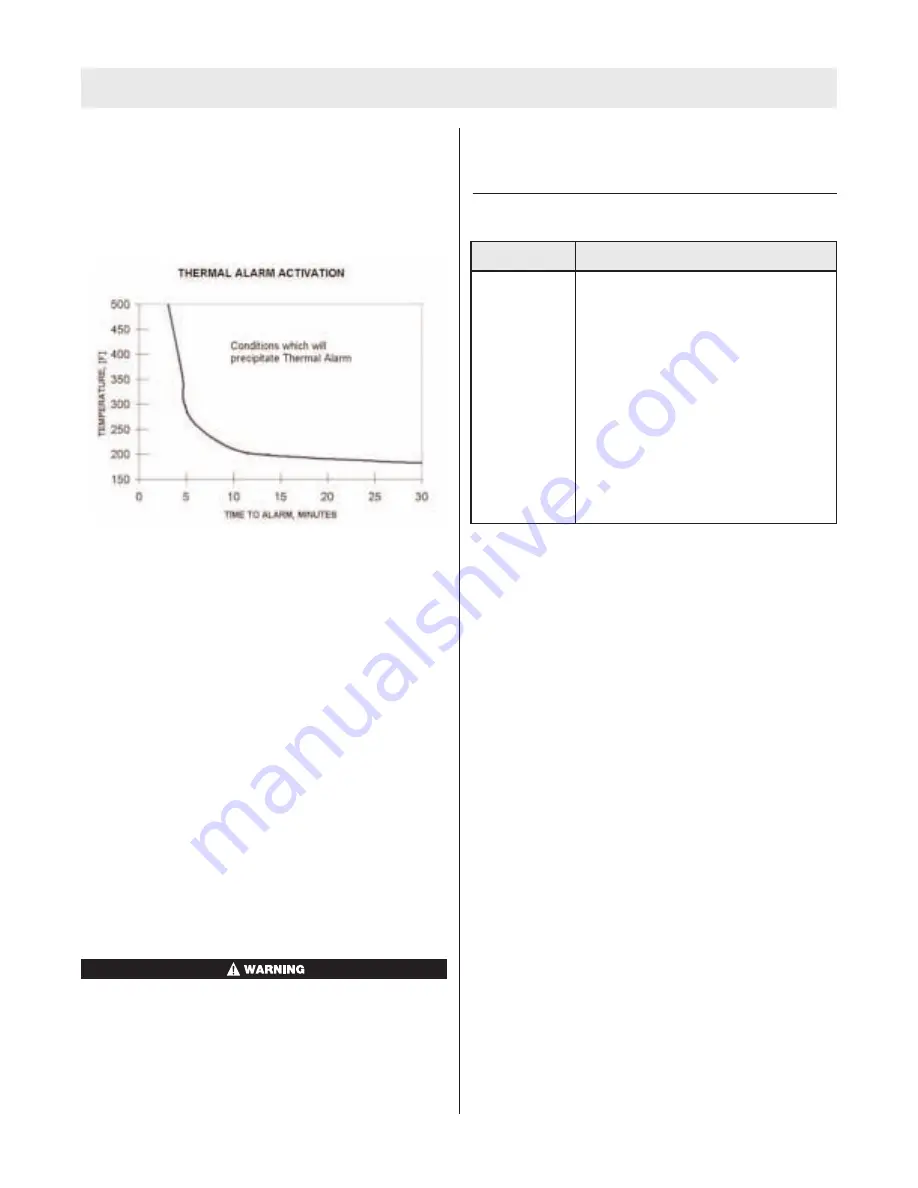
Chart 3 shows the ICM Tx Unit thermal alarm activation
curve. The time/temperature limits are based on the
curve. The thermal alarm sounds if the pre-set limit
exceeds the curve. The alarm will self-cancel depending
on the severity of conditions. This may occur even though
the temperature is above the thermal curve.
Chart 3: ICM Tx Unit Thermal Alarm Activation Curve
Note:
This chart was generated from data obtained in a
laboratory setting and is for reference only. Conditions
are highly variable in an actual use scenario. Users of the
ICM Tx Unit with the thermal alarm option should develop
procedures for the use of this feature.
Optional ID Tag (PN 10058545), for use with ICM Tx
Unit
The purpose of the ID Tag is to associate a name ID or
truck and jump seat location with the ICM Tx Unit. Once
the ICM Tx Unit has read the ID data from a tag, that ID
will be associated with that ICM Tx Unit for the purpose of
organizing the data log. By default, a name ID will remain
associated with the ICM Tx Unit for 24 hours before expir-
ing (12 hours for devices manufactured before June
2006). The ICM Tx Unit can be configured to retain name
ID information until another name ID tag is read. For
instructions on changing this setting, refer to the ICM Tx
Unit Data Program Software Instructions (P/N 10067066).
The ID Tag has a space for the user to place a label in
which the ID information can be written on the outside of
the ID Tag for easy identification. This space is located
on the side of the ID Tag opposite the approval label.
Any label attached to the ID tag must be less than 4
square centimeters in total area; otherwise, the
Intrinsic Safety Approval is void. Failure to follow this
warning can result in serious personal injury or death.
Before using the ID tag, inspect for damage or cracks in
the case. If damage is found, discard and replace the ID
tag.
SPECIFICATIONS
Chart 4: ICM Tx Unit Specifications
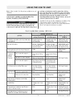
Functional Check of the ICM Tx Unit
1. Don the SCBA following the instructions in the SCBA
User’s Instruction Manual.
2. When opening the cylinder valve to perform the SCBA
“system checks,” listen for the ICM Tx Unit automatic
activation indicator as described in table.
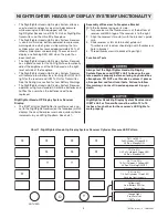
3. Look through the facepiece lens at the LED panel, the
LEDs should illuminate through the startup sequence
as the SCBA is pressurized. The startup sequence is
as follows:
a. One Red LED ON/OFF
b. One Orange LED ON/OFF
c. One Yellow LED ON/OFF
d. Four Green LED ON/OFF
e. Three Green LED ON/OFF
f. Two Yellow LED ON/OFF
g. One Red LED ON/OFF
4. Look to verify that the GREEN light on the ICM Tx Unit
is slowly flashing.
5. Stand motionless for approximately 20 seconds.
Listen for the pre-alarm to sound the low volume
repeated tones. Look for the RED light on the ICM Tx
Unit to alternately flash slowly.
6. Remain motionless until the full alarm activates. Listen
for the alarm to sound the increasing loud repeated
tones. Look for the light to flash RED rapidly.
7. Reset the ICM Tx Unit by pushing the RESET (yellow)
button on the side of the unit 2 times within approxi-
mately 1 second.
USING THE ICM TX UNIT
10
TAL 709 (L) Rev. 4 - 10058881
SPECIFICATIONS
Weight
1.0 pounds (approximately 450 grams
w/battery)
Alarm Output
Greater than 95dBA at 3 meters
Battery
Four AA Batteries
Battery Life
25 hours in full alarm mode
Electronics
Microprocessor controlled
Standards
Listed as intrinsically safe to ANSI UL
913
NIOSH certified for use on MMR SCBA
Not evaluated by MSHA for use in
explosive atmospheres


