


!
7898 Zionsville Road
Indianapolis, Indiana 46268
Telephone: (317) 842-2545
www.mssedco.com
Page 5
S-CORv0917
Spectrum Coordinator
INSTALLATION INSTRUCTIONS
S-COR
h
ClearPat
™
Section 6
Programming the Coordinator
Vestibule Openings: Secondary S-COR (Fig. 3)
Upon Power Up, the screen will read “MS Sedco Press
Select To Begin”. Press Select. The next screen will show
“Opening Type”. The default is Single. Use the arrows to
choose Vestibule, then press Select.
The next screen will show Vestibule Primary press > button
and Vestibule Secondary will appear on screen. Press
Select and the screen will show, “Press < Button Pair To
Primary” for 2 minutes.
WARNING:
The Primary S-COR must be powered
up and on the proper screen simultaneously for
successful pairing.
Prior to pressing the < button on the Secondary
Coordinator, the Primary Coordinator must be on the
proper screen to accept pairing. On the Primary
Coordinator press Select until the “Pair Device” screen is
showing. Press the > button until “Secondary” is
displayed, press Select and the screen should show
“Press Device Pair Button”. At this time press the <
button on the Secondary S-COR until the screen shows
“Press < Button Found Coordinator” and the Primary
Coordinator screen shows “IDxxxx Paired Press Select”
for a successful pairing. In the event the pairing was not
successful the screen will show “Pair Failed Press Select”
after 2 minutes. In either case, pressing Select will give
you the option to pair the Secondary S-COR again.
NOTE:
Once the Secondary S-COR is
successfully paired, the Vestibule Delay Time
must be set in Add Settings ON THE PRIMARY
COORDINATOR.
The next screen will show “Channel Select.” Four
channels are available, with the default being channel 1.
In most cases, the channel will remain at the default, but
should one wish to auto scan to the cleanest channel, or
manually choose a different channel for better
performance when two openings are in close proximity,
this can be accomplished by using the arrow keys. (Note
that in manual mode, the current channel selection will
be indicated with an asterisk (*), then press Select.
The next screen will read “Add Setting.” This is the place
where users can program additional features into the
device. Two additional settings on the Secondary Coordi
-
nator are available: Output Delay and SecureActivation.
These are covered below:
Output Delay
– This controls the delay time between
output relays 1 and 2 and can be adjusted via the arrow
keys. Remember, Output 1 is typically the locking device,
and Output 2 is typically an automatic door. After adjust
-
ing time with the arrow keys, press Select to move on to
the next step.
SecureActivation
– Many times an automatic door with
wireless activation is installed after a security system is
already in place. SecureActivation allows the outside
Transceiver to be integrated into the security system.
When SecureActivation is turned on, the outside switch
will not activate the door unless given clearance from the
security system. There are two choices for turning “On”
this feature, Normally Open (N.O.) and Normally Closed
(N.C.), depending on whether the circuit is normally open
or normally closed. Once programming is complete,
connect the SecureActivation 2-wire harness included to
the Normally Open (N.O.) and Common (COM) of the
security device and plug the harness into the
SecureActivation socket on the S-COR (Figure 1).
WARNING:
The Security Clearance input requires
a dry contact. Do not apply voltage!
Section 7
Operational Mode
In operational mode, whenever a Transceiver is activated,
the Coordinator screen will display the following informa
-
tion: ID, battery status and signal transmission strength
(see Figure 4).
!
!
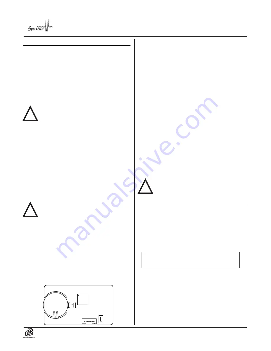
FIGURE 2
TRX Transceiver Circuit Board
CR2032
Battery
PAIR BUTT
ON
FIGURE 4
S-COR Screen when S-TRX is Activated
IDXXXX
****
Battery OK
Transceiver ID:
4 digit automatically assigned
Signal Strength:
**** Optimal
***
Good
**
OK
*
Weak
Battery Status:
Battery OK
Replace Battery


