background image

Page 4

(82A022)  CP/RXv0913

MODE #2—Receiver With Adjustable Time Delay Output

(Releases Electric Locking Devices)

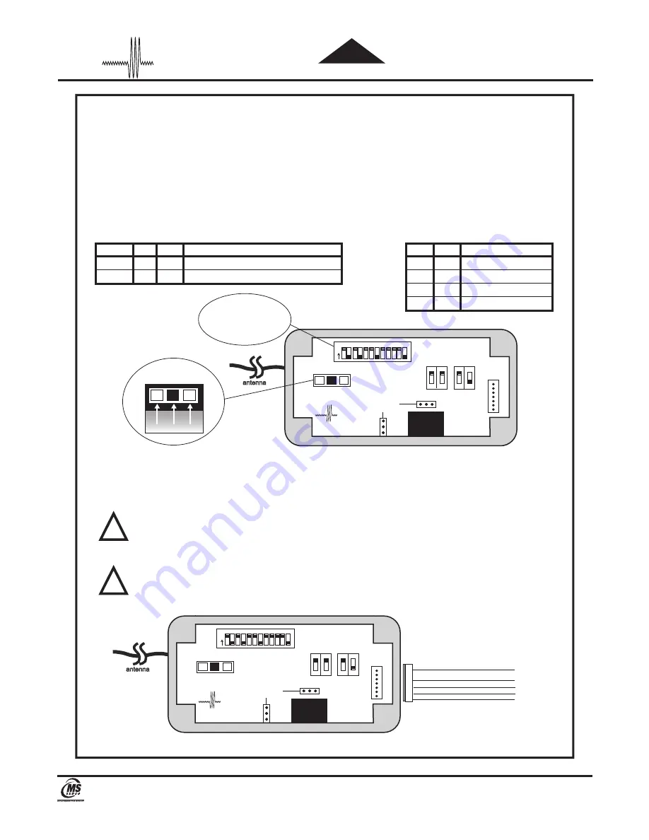
1.  SELECT FREQUENCY:  Remove CP/RX cover and select the desired frequency to match the 

  transmitters via the 3-position slide switch on the receiver circuit board (Fig. 1).

2.  SELECT SECURITY CODE:  Select the desired security code to match the transmitters via the 12 dip 

  switches on the CP/RX circuit board (Fig. 1).

3.  SELECT OPERATING MODE:  Using the Table 1 select Mode #2 via the dip switches marked C & D 

  located on the CP/RX circuit board (Fig. 1).

4.  SELECT TIME DELAY:  Using Table 2 select the desired time delay via the dip switches marked A & B 

  on the CP/RX printed circuit board (Fig. 1).

5.  Mount the CP/RX in its intended location and plug in the provided wiring harness.

6.  Connect device to be controlled to appropriate wires (Fig. 2).

7.  Connect power to the appropriate wires (Fig. 2).

8.  Activate the CP/RX to verify the system is working properly.  If further time delay adjustment is 

  required to the unit, refer back to step 4.


ATTENTION: 

 Changing the operating mode or time delay settings after power is applied requires a 6 


second delay for the new programming to take effect.

9.  Install CP/RX cover with 4 screws provided.


ATTENTION: 

 If CP/RX is installed inside a door operator housing, drill a small hole in 


the housing and pull the receiver antenna wire through it to ensure radio reception is not 


inhibited.

Figure 2

!

!

Table 1

Table 2

Figure 1

 Mode#  C 


Operating Mode

  1 

OFF  OFF  Normal Receiver (Factory Setting)

  2 

ON  OFF  Receiver with Time Delayed Output

  A 


Time Delay

  ON 

ON   

5 Seconds

  ON  OFF   

10 Seconds

 OFF  ON   

15 Seconds

 OFF  OFF    20 Seconds

antenna

RELAY 1

  1  2  3  4  5  6  7  8  9  10  11  12

O

N

WIRE 

HARNESS 

PLUG

ADD ON MODULE 

PLUGS

ClearPath

CP/RX

HDRC™ Program 1-12

300 MHz Program 1-10

390 MHz Program 1-12

12 POSITION SECURITY 

CODE SWITCH

300MHz

390MHz

HDRC™

FREQUENCY SELECTION 

SWITCH

Input Voltage:  12 - 24V AC or DC, RED + (POS), BLACK - (NEG)

*Surge suppression circuitry is built in.  Therefore it can directly drive Mag Locks or Electric Strikes without additional protection.

WHT

BROWN

VIO

N.C.

COM

N.O.

RED
BLK

+

-

12-40V AC 

OR DC

1
3
5

6

7

antenna

300MHz

390MHz

HDRC™

FREQUENCY SELECTION 

SWITCH

RELAY 1

  1  2  3  4  5  6  7  8  9  10  11  12

O

N

WIRE 

HARNESS 

PLUG

ADD ON MODULE 

PLUGS

ClearPath

CP/RX

OPERATING 

MODE 

SELECTION 

SWITCH

on

on

A     B

TIME DELAY 

SELECTION 

SWITCH

on

on

C     D

OPERATING 

MODE 

SELECTION 

SWITCH

on

on

A     B

TIME DELAY 

SELECTION 

SWITCH

on

on

C     D

             CP/RX


Multi-Mode Radio Receiver and Timing Module 

INSTALLATION INSTRUCTIONS

HDRC

h

ClearPat

8701 Castle Park Drive 

 Indianapolis, Indiana 46256

Telephone: (317) 842-2545 

 www.mssedco.com 

 [email protected]

Summary of Contents for ClearPath HDRC CP/RX

Page 1: ...ion The physical placement of the CP RX is typically in the door operator housing area since the power supply and operator control are already in this location however optimum performance is achieved with the unit located outside the door operator housing ATTENTION The antenna wire on the receiver must be exposed outside the operator housing Drill a small hole in the housing and expose as much of ...

Page 2: ...interference is affecting the signal changing frequencies may correct this problem It is important to remember that regardless of the frequency settings both the transmitter and receiver must match 6 If the receiver is not responding to a signal from the transmitter there are a few additional things to consider Materials such as metal energy efficient Low E glass or other electronic devices may af...

Page 3: ...ure radio reception is not inhibited Figure 2 Figure 1 antenna RELAY 1 WIRE HARNESS PLUG ADD ON MODULE PLUGS ClearPath CP RX HDRC Program 1 12 300 MHz Program 1 10 390 MHz Program 1 12 12 POSITION SECURITY CODE SWITCH 300MHz 390MHz HDRC FREQUENCY SELECTION SWITCH Input Voltage 12 24V AC or DC RED POS BLACK NEG Surge suppression circuitry is built in Therefore it can directly drive Mag Locks or Ele...

Page 4: ...d ATTENTION If CP RX is installed inside a door operator housing drill a small hole in the housing and pull the receiver antenna wire through it to ensure radio reception is not inhibited Figure 2 Table 1 Table 2 Figure 1 Mode C D Operating Mode 1 OFF OFF Normal Receiver Factory Setting 2 ON OFF Receiver with Time Delayed Output A B Time Delay ON ON 5 Seconds ON OFF 10 Seconds OFF ON 15 Seconds OF...

Page 5: ...the CP RX in its intended location and plug the 5 lead wiring harness provided into its connector on the CP RX circuit board Fig 3 7 Connect each device to be controlled to the appropriate wires Fig 3 8 Connect power to the appropriate wires Fig 3 ATTENTION Changing the operating mode or time delay settings after power is applied requires a 6 second delay for the new programming to take effect 9 I...

Page 6: ...er time delay adjustment is required to the unit refer back to step 4 ATTENTION Changing the operating mode or time delay settings after power is applied requires a 6 second delay for the new programming to take effect 10 Install CP RX cover with 4 screws provided ATTENTION If CP RX is installed inside a door operator housing drill a small hole in the housing and pull the receiver antenna wire thr...

Page 7: ...he new programming to take effect 8 Install CP RX cover with 4 screws provided ATTENTION If CP RX is installed inside a door operator housing drill a small hole in the housing and pull the receiver antenna wire through it to ensure radio reception is not inhibited Table 1 Figure 1 HDRC Program 1 12 300 MHz Program 1 10 390 MHz Program 1 12 12 POSITION SECURITY CODE SWITCH antenna RELAY 1 1 2 3 4 5...

Reviews: