background image

3

Trouble Shooting

General Trouble Shooting

It takes the Command Station, the decoders and your layout to make the

DCC system work. This Trouble Shooting Section has been arranged in a

manner easiest for you to find the cause of your problem. Please go

through this section in the 

exact 

order it appears because each following

set of instructions assumes that the preceding set has been tested and

that component of the DCC system found not defective.

1. Turn on the power of the base unit. The power light should turn on

.

If not, make sure the power supply is securely plugged into the base unit

and into a working AC wall outlet. Then turn off the power, wait 3 seconds

and turn on the power again. If power light still does not turn on, send the

unit in for repair.

2. The fan should not spin when there is no load. 

If the fan turns on

(spins slowly) and off periodically, it indicates there is an overload or short

circuit. Short circuits could be caused by a piece of metal lying across the

track, a defective decoder, a derailed loco, faulty turnouts, or a non-

insulated reverse loop.

3. Check the Main Track output.

 Place an analog loco or test light on the

Main Track. The loco should buzz or the test light should light. If not, check

all connections and make sure the rear green plug is securely plugged in.

Make sure the screws on the green plug are tightened on the wire and not on

the wire cover (insulator). If the analog loco still does not buzz or the test

light does not light, send the unit in for repair.

4. LCD does not display anything. 

The Cab LCD should display the

current loco when the power is on. If not, plug the Cab into another Cab

Jack on the base unit. If the LCD still does not display anything, send the

unit in for repair.

5. Check the communication between the base unit and the Cab.

Press 

2

. F2 should momentarily display on the LCD and the Link light

should blink. If not, set the Cab to be the Master Cab (Cab #1) by pressing

SYS, 6, 1, 

and

 ENTER. 

Make sure there is no other Master Cab in the

system and try again. If there is still no communication, send the unit in for

repair. If there is communication, you may have the wrong Cab setup.

Read the Cab Setup section.

6. Your loco may have a pickup problem. 

You should periodically clean

your track and your loco’s wheels. Oxide coating or dirt on either the track

or loco’s wheels often causes intermittent and jerky operation.

If you pass the above steps, your Command Station and Cabs are

fine. The problem may lie in the decoder.

7. Your decoder may have lost its memory or is in Advanced Consist

mode (CV19 is not 0).

 Reprogram the loco address and try again.

8. Your decoder may have too much momentum

. Program the loco with

zero acceleration and deceleration rates.

MRC Prodigy Advance

2

Trouble Shooting  3-1

Summary of Contents for 0001414

Page 1: ...MRC Prodigy Advance2 User s Manual...

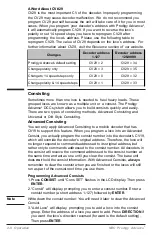
Page 2: ...er Values on the Program Track 2 6 Configuration Variables CVs 2 7 Most Commonly Used CVs 2 7 A Word About CV 29 2 8 Consisting 2 8 Advanced Consisting 2 8 Programming Advanced Consists 2 8 Running Ad...

Page 3: ...ecoders installed in your locos that receive the DCC commands Each decoder equipped loco has its own address Each decoder receives DCC commands but only follows those commands matching its address No...

Page 4: ...in Track Read Loco on Program Track System Menu Summary Chart Most functions are initiated by pressing their associated keys However there are ten functions initiated by pressing the SYS key followed...

Page 5: ...efault address 3 If you purchase a decoder equipped loco its address may be its road number Read your decoder and or loco manual for your decoder address To select a loco press the LOCO key Using the...

Page 6: ...incremental steps the loco takes to go from 0 to top speed There are three speed steps 14 28 and 128 The higher the speed steps setting the higher the number of different speeds on which the loco can...

Page 7: ...unit will stop Main Track output for 2 seconds then resume and the fan will turn on spins slowly and off periodically Please remove the overload or short circuit for proper operation When operating l...

Page 8: ...using 8 Cabs or less set all Cab addresses sequentially starting from 1 and turn the Cab select switch on the base unit to the 1 8 position This prevents the base unit from trying to communicate to Ca...

Page 9: ...o with a start voltage so that it will begin to move as soon as the throttle is turned Top Voltage The top voltage top speed is the voltage speed at full throttle The Prodigy Advance top end voltage i...

Page 10: ...ram Track for programming However you have to know the loco address in order to program on the Main Track Otherwise you have to program the loco on the Program Track Not all decoders support the Progr...

Page 11: ...ables also known as CVs receive and hold entered data that allow the decoder to be tailored to a specific loco or accessory Some CVs are also called registers The Prodigy Advance2 DCC system allows yo...

Page 12: ...s CV19 which will override the decoder s original address Therefore the loco will no longer respond to commands addressed to its original address but rather only to commands addressed to the consist...

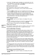
Page 13: ...d on the Program Track or program CV19 to zero Universal Old Style Consisting This feature allows you to use older decoders that do not have CV19 to support Advanced Consisting In this type of consist...

Page 14: ...Turn the throttle and all the locos in the consist will start moving together 4 To control accessory functions use each loco s original address The above LCD display shows a Universal Consist group le...

Page 15: ...le pole double throw DPDT switch It allows you to change the polarity of the reverse loop section Before a loco crosses the first insulated gap you must make sure the polarity of reverse loop section...

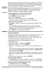
Page 16: ...ne with accessory 3 Press ENTER to escape accessory operation Accessory Routes Grouping of turnouts or accessories can be consisted to form a route The Prodigy Advance2 DCC system allows up to 31 rout...

Page 17: ...is securely plugged in Make sure the screws on the green plug are tightened on the wire and not on the wire cover insulator If the analog loco still does not buzz or the test light does not light send...

Page 18: ...short circuits and or stray objects lying across track rails 9 Make sure the Link light flashes when you press F2 Special Trouble Shooting Base unit power light is on but Cab does not display anything...

Page 19: ...le to program on the Main Track to set an Advanced Consist Your Prodigy Advance2 DCC has been thoroughly tested at the factory Do not shut down your layout unnecessarily Before returning your unit for...

Page 20: ...d steps are as follows 1 Press Prog to select Prog Prog Track 2 Press Enter six times until CV displays on the screen 3 To select CV29 press 29 and Enter 4 CV data displays Press 2 and Enter 5 CV disp...

Reviews: