BA2053/09/05 DE-EN . MESSKO INSTRUMENTS
MESSKO
®
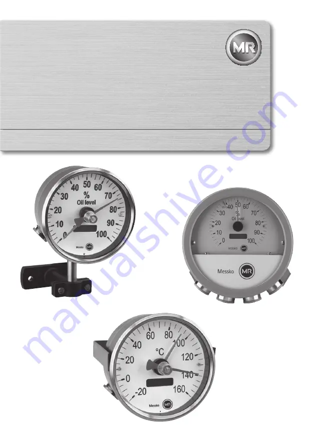
EI100, EI100/160
ELEKTRONISCHE FERNANZEIGE
ELEKTRONIC INDICATOR
Betriebsanleitung / Operating Instructions
Page 1: ...BA2053 09 05 DE EN MESSKO INSTRUMENTS MESSKO EI100 EI100 160 ELEKTRONISCHE FERNANZEIGE ELEKTRONIC INDICATOR Betriebsanleitung Operating Instructions ...
Page 2: ...BA2053 09 05 2 ...
Page 3: ...ung aufbewahren Contents 1 Safety 4 1 1 Safety instructions 4 1 2 Specified application 4 1 3 Important notes on equipment operation 4 2 Product specification 5 3 Installation 6 4 Electrical connections 6 4 1 Power supply 24VDC 6 4 2 Sensor input 4 20mA 6 5 Function test 8 6 Technical data 8 7 Installation diagram 9 7 1 EI100 on stand 9 7 2 EI100 with clamp strap 10 7 3 EI100 160 10 8 Circuit diag...
Page 4: ...bliged to comply with the national health safety regulations It is especially emphasized that tasks performed on live i e dangerous contact components are permissible only while these components are either de energized or protected against direct contact 1 2 Bestimmungsgemäße Verwendung Die Temperaturfernanzeige EI100 bzw EI100 160 dient der Fernanzeige beliebiger Sensorsignale Die analogen Sensor...
Page 5: ...ical installation is subject to the relevant national safety regulations It is imperative to connect the protective conductor in order to ensure trouble free operation 2 Product specification The remote electronic indicator El100 or EI100 160 shows the temperature or a modulation in percent of any desired sensor This is indicated by an analog pointer instrument and a digital LCD display The input ...
Page 6: ...until the device is completely connected 4 2 Sensoreingang 4 20mA There are two ways to connect the 4 20mA signal of the sensor I1 Passive sensor without own power supply I2 Active sensor or active 4 20mA current circuit With both types of connection remember the maximum load of the sensor Sensor input I1 passiv The passive input delivers a voltage of 24V DC Connect the lines as shown in the circu...
Page 7: ...20mA Examples of passive sensors A Oil temperature Thermometer MT ST 160 SK TT or combi sleeve TT See current circuit diagram 8 1 page 11 B Winding temperature Thermometer MT ST 160W TTor ZT F2 TT See current circuit diagram 8 2 page 12 Sensor input I2 active Connect the lines as shown in the circuit diagram figure 5 EI100 or figure 6 EI100 160 to the and terminals Examples of active sensors C Oil...
Page 8: ...sseingang Sensorversorgung Versorgungsspannung UV ca 3V für passiven Sensoreingang 5 Function test Check the electrical connection of the El 100 or EI100 160 using the circuit diagram in chapter 8 Switch on the power supply The value shown must correspond to the value of the sensor Take the tolerances from the data sheets of the equipment that is connected 6 Technical data Housing EI100 Dimension ...
Page 9: ...IEC 60068 2 32 Isolationsspannungstest IEC 60255 5 7 Maßzeichnungen 7 1 EI100 mit Stativ Testing Reports Test Standard Sustained load capacity VDE 0435 part 303 Short term current VDE 0435 part 303 Fault stability impulses IEC 61000 4 4 Fault stability HF IEC 61000 4 6 Fault stability discharge IEC 61000 4 2 Fault stability power cut IEC 61000 4 11 Fault stability surge IEC 61000 4 5 Fault stabili...
Page 10: ...it Klemmbügel 7 2 EI100 with clamp strap 7 3 EI100 160 7 3 EI100 160 Bild 8 EI100 mit Klemmbügel Fig 8 EI100 with clamp strap Bild 9 EI100 160 Fig 9 EI100 160 7 Maßzeichnungen Dimensional drawings Tel 49 6171 63 98 0 Fax 63 98 98 ...
Page 11: ...BA2053 09 05 11 8 Stromlaufpläne Circuit diagrams 8 Stromlaufpläne 8 1 Öltemperatur passiver Sensor 8 Circuit diagrams 8 1 Oil temperature passive sensor Bild 10 Fig 10 24VDC 4 20mA R I I1 I 2 R I ϑ ...
Page 12: ...BA2053 09 05 12 8 Stromlaufpläne Circuit diagrams 8 2 Wicklungstemperatur passiver Sensor 8 2 Winding temperature passive sensor Bild 11 Fig 11 Ω Ω Ω Ω Ω Ω Ω Ω Ω Ω Ω Ω Ω 24VDC 4 20mA R I I1 I 2 R I ...
Page 13: ...re active sensor Bild 12 Fig 12 8 Stromlaufpläne Circuit diagrams 24VDC 4 20mA R I I1 I 2 R I Messko 2 1 3 4 6 5 TRIP ERROR POWER ALARM S 4 S 3 S 2 S 1 22 21 23 24 25 13 7 8 11 9 10 12 16 15 14 18 17 19 20 EPT 202 35 30 28 27 26 29 31 32 33 34 37 36 39 38 40 41 42 43 ...
Page 14: ...ur aktiver Sensor 8 4 Winding temperature active sensor Bild 13 Fig 13 36 39 38 40 41 42 43 24VDC 4 20mA R I I1 I 2 R I Messko 2 1 3 4 6 5 TRIP ERROR POWER ALARM S 4 S 3 S 2 S 1 22 21 23 24 25 13 7 8 11 9 10 12 16 15 14 18 17 19 20 EPT 202 35 30 28 27 26 29 31 32 33 34 37 ...
Page 15: ...BA2053 09 05 15 Bild 14 Fig 14 8 Stromlaufpläne Circuit diagrams 8 5 Ölstand aktiver Sensor 8 5 Oil level active sensor ...
Page 16: ...49 6171 6398 0 Fax 49 6171 6398 98 Email info messko com www messko com Please note The data in our publications may differ from the data of the devices delivered We reserve the right to make changes without notice BA2053 09 05 DE EN MESSKO EI100 EI100 160 MS99087301 06 14 Messko GmbH 2014 ...