mr
.
steam
®
Electric Towel Warmers
Installation and Operating Instructions
________________________________________________________________
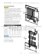
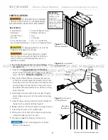
2. Slide the Towel Warmer with assembled inserts into the
brackets and secure the Towel Warmer by tightening the
bracket set screws provided (see figure 3). Secure junc-
tion box cover with screws provided. (Use longer screws
as required by construction conditions.)
The connected wires should be placed
inside junction box before securing junction box cover.
DIGITAL PROGRAMMABLE TIMER
Installation:
1. Read the operating instructions provided with the timer.
2. Disconnect power supply prior to installation to prevent
electrical shock.
3. Damage to the contacts caused by short circuiting will
void the warranty.
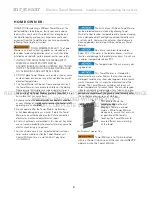
4. DO NOT place Towel Warmer units inside a shower, sauna
or steam room enclosure or any other wet location or with
elevated temperatures.
5. Wire in accordance with National Electrical and Local
Code requirements. Be sure all connections are secure.
Double check all twist-on wire connectors.
9
ELECTRICAL CONNECTIONS
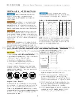
TO PREVENT SHOCK HAZARD, TURN OFF ELECTRICITY AT
THE MAIN PANEL BEFORE WIRING. VERIFY WITH MULTIMETER.
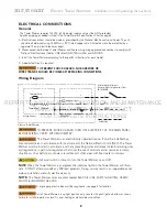
All wiring must conform to National Electrical and Local Codes.
The Towel Warmer is an electronically oper-
ated device. It must be installed by a licensed electrician in
accordance with local code and the National Electric Code
(NEC).
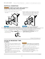
5. Mount timer into wall box using supplied screws.
6. If timer does not operate, check that the timer’s black wire
is connected to hot line and not the load. If necessary,
reverse connections to red and black wires
7. When the indicator light on the Towel Warmer is illumi-
nated, the Towel Warmer is energized.
PUR
103930 7.17
2
”
x 4
”
Junction
Box
Junction
Box Cover
Wiring
Box
NM 120VAC wiring
NOTE
:
Secure connected
wires with wire nuts
Junction Box
Set Screw
1. Connect wiring per instructions page 8, Electrical
Connections
NM (non-metallic) cable, if permitted by
National and Local Codes may be used instead of BX cable
Drawings for illustrative purposes only
3. Use the set screw to secure
the wiring box to the junction
box cover (as shown).
4. After properly installing Towel Warmer. Turn ON electric-
ity at the main panel. Turn ON the Towel Warmer and
allow 30+ minutes to warm up.
REFER
Nationa
Nationa
TO
and Loc
and Loc
INSTALLATION,
l Codes may be used instead of BX cab
l Codes may be used instead of BX c
OPERATION
inside junction box befor
inside junction box befor
ee
AND
securing ju
securing ju
MAINTENANCE
ction box cover.
ction box cover.
MANUAL PROVIDED
OV
P
4 Aff
WITH
ll
PRODUCT
ll
T
l W
T
T
O
FOR
J
J
unction
unction
COMPLETE
M
E
PLE
M
nction Box
nction Box
Set Screw
Set Screw
INSTRUCTIONS
y at the main panel.
y at the main panel. T
Turn ON the
urn ON the T
Towe
owe
ll
30
ll
30


