mr
.
steam
®
Electric Towel Warmers
Installation and Operating Instructions
________________________________________________________________
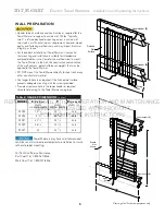
WALL PREPARATION
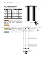
UÊi>`iÀÊÌÊLiÊvÊ>ÌiÀ>ÃÊ>`ÊVÃÌÀÕVÌÊ>ÃÊÀiµÕÀi`ÊvÀÊÌ iÊ
Towel Warmer to support a minimum of 120 lbs. Typically,
two 2” x 6” wooden header spanning across a minimum of
two studs is a sufficient minimum requirement, however, wood
quality and fastening methods vary and may impact structural
integrity, as shown.
UÊÀÊÌ iÊVÀÀiVÌÊÃÌ>>ÌÊvÊ/ÜiÊ7>ÀiÀÊÌÊÃÊiÃÃiÌ>Ê
that mounting and installation is suitable for intended use
and predictable misuse. Consider the method used to mount
the Towel Warmer to the wall, the construction and condition
of the wall and any potential forces or weights that may be
applied to the Towel Warmer.
UÊ"Ê "/ÊÕÌÊÌ iÊ/ÜiÊ7>ÀiÀÊ`ÀiVÌÞÊÌÊÃ iiÌÊÀVÊÀÊ>ÞÊ
other non-structural material.
UÊ1ÃiÊ}iÀÊv>ÃÌiiÀÃÊ>ÃÊÀiµÕÀi`ÊvÊÌ iÊwà i`ÊÜ>ÊÃÕÀv>ViÊ
prevents adequate mounting with the screws provided.
UÊ*ÀÛ`iÊ>ÊVi>À>ViÊ iÊÊÌ iÊÜiÀÊ i>`iÀÊ>ÃÊÀiµÕÀi`Ê
to route field wiring to the Towel Warmer wiring box.
Towel Warmers may have small dimensional
variations and must be measured prior to installation to insure
safe and proper mounting.
For Technical Service Assistance:
East Coast Tel: 1-800-767-8326
West Coast Tel: 1-800-727-8326
Y
Upper Header
(Z)
Lower Header
(Z)
Wiring
Box
Finished
Wall
Surface
Finished
Wall
Surface
Y
Upper Header
(Z)
Lower Header
(Z)
Wiring
Box
5
Drawings for illustrative purposes only
Table 2: HEADER DIMENSIONS
(inches)
MODEL X
(minimum)
Y Z
(minimum)
HEADER
HEADER
HEADER
SIZE
HORIZONTAL
LENGTH
VERTICAL
LENGTH
___________________________________________________________________
WX24
18
3/4
20
1/2
2 x 6
___________________________________________________________________
WX36
9
1/2
30
3/4
2 x 6
___________________________________________________________________
WX41
22
1/2
35
1/2
2 x 6
___________________________________________________________________
WX29
26
1/4
22
1/8
2 x 6
___________________________________________________________________
WX27
22
22
1/2
2 x 6
REFER
F
MOD
MOD
O
X
T
EL
L
ON,
Z
Z
(min
(mi
HEADE
D
ALLATIO
Y
Y
HEADER
INSTA
(minimum)
minimum)
HEADER
A
O
OPER
R
RATION
ON
ON
O
P
mum)
mum)
AND
AN
AN
CE
MAINTENANC
UAL
VERTICAL
VERTIC
__________
______
MANU
ONTAL
ONTA LENGTH
LENGTH
______________
______________
33
U
OVIDED
E
_______________
_______________
PRO
ENGTH
ENGTH
_________
________
O
_
WITH
H
H
TH
PRODUCT
UCT
UCT
PR
R
R
_____
____
FOR
_________
_________
R
_
PLETE
E
_______________
_____________
2 x 6
2 x 6
COMP
______________
______________
30
30
33//44
P
_
IN
NSTRUCTIONS
R
TRUC ONS
T


