background image

DCA300SSJU4F2 60 HZ GENERATOR• OPERATION MANUAL — REV. #0 (06/26/18) — PAGE 63

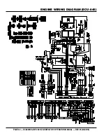
ENGINE WIRING DIAGRAM (BASLER DGC2020HD OPTION)

Summary of Contents for WHISPERWATT DCA300SSJU4F2

Page 1: ...EQUIPMENT AT ALL TIMES To find the latest revision of this publication visit our website at www mqpower com WHISPERWATT SERIES MODEL DCA300SSJU4F2 60Hz GENERATOR JOHN DEERE 6090HFG06 DIESEL ENGINE Revision 0 06 26 18 OPERATION MANUAL ...

Page 2: ...PAGE 2 DCA300SSJU4F2 60 HZ GENERATOR OPERATION MANUAL REV 0 06 26 18 PROPOSITION 65 WARNING Diesel engine exhaust and some of ...

Page 3: ...nel Option 26 27 Output Terminal Panel Familiarization 28 30 Load Application 31 Generator Outputs 32 33 Generator Outputs Gauge Reading 33 Output Terminal Panel Connections 34 35 Inspection Setup 36 40 Generator Start Up Procedure Manual 41 42 Generator Start Up Procedure Auto Mode 43 Generator Shut Down Procedures 44 Maintenance 45 60 Generator Wiring Diagram 61 Engine Wiring Diagram ECU 845 62 ...

Page 4: ... control uids from an external source It is the operator s responsibility to monitor uid levels at all times DO NOT EXCEED THE RECOMMENDED MAXIMUM CAPACITY ENVIRONMENTAL P N M91110000 DANGER Using a generator indoors CAN KILL YOU IN MINUTES 120 V OFF GAC 2 2H POWERED by Honda Engines 120V 15A GR PRISE DE TERRE AC CIRCUIT BREAKER INTERRUPTEUR DE COURANT PRINCIPAL NEUTRAL BONDED TO FRAME NEUTRE MIS ...

Page 5: ...fety messages specifically address the level of exposure to the operator and are preceded by one of four words DANGER WARNING CAUTION or NOTICE SAFETY SYMBOLS DANGER Indicates a hazardous situation which if not avoided WILL result in DEATH or SERIOUS INJURY WARNING Indicates a hazardous situation which if not avoided COULD result in DEATH or SERIOUS INJURY CAUTION Indicates a hazardous situation w...

Page 6: ...ecommended by MQ Power for this generator Damage to the generator and or injury to user may result ALWAYS know the location of the nearest fire extinguisher ALWAYS know the location of the nearest first aid kit ALWAYS know the location of the nearest phone or keep a phone on the job site Also know the phone numbers of the nearest ambulance doctor and fire department This information will be invalu...

Page 7: ...n NEVER tamper with the factory settings of the engine or engine governor Damage to the engine or generator can result if operating in speed ranges above the maximum allowable Wet stacking is a common problem with diesel engines which are operated for extended periods with light or no load applied When a diesel engine operates without sufficient load less than 40 of the rated output it will not op...

Page 8: ...it breakers OFF before performing maintenance on the generator or making contact with output terminals NEVER insert any objects into the output receptacles during operation This is extremely dangerous The possibility exists of electrical shock electrocution or death Backfeed to a utility system can cause electrocution and or property damage NEVER connect the generator to a building s electrical sy...

Page 9: ...ose the battery to open flames sparks cigarettes etc The battery contains combustible gases and liquids If these gases and liquids come into contact with a flame or spark an explosion could occur WARNING ALWAYS wear safety glasses when handling the battery to avoid eye irritation The battery contains acids that can cause injury to the eyes and skin Use well insulated gloves when picking up the bat...

Page 10: ...ame and all other metal parts be sent to a recycling center Metal recycling involves the collection of metal from discarded products and its transformation into raw materials to use in manufacturing a new product Recyclers and manufacturers alike promote the process of recycling metal Using a metal recycling center promotes energy cost savings EMISSIONS INFORMATION NOTICE The diesel engine used in...

Page 11: ...ngine Specifications Model John Deere 6090HFG09 EPA Tier 4 Final Certified Type 4 cycle water cooled direct injection turbo charged charged air cooled EGR DOC and SCR No of Cylinders 6 cylinders Bore x Stroke 4 64 in x 5 34 in 118 4 mm x 136 mm Displacement 549 2 cu in 9 0 liter Rated Output 437 HP 326 kW at 1800 rpm Starting Electric Cold Weather Starting Aid NVT Dieselmatic Starting Fluid System...

Page 12: ...ge Program Exit Option ECU PSI OIL PRESS 0 25 50 75 100 F WATER TEMP 100 140 180 220 260 F FUEL E F RPMX10 SPEED 0 120 150 180 210 60 F DEF E F ECU Integrated Gauge Panel VOLTS 0 12 18 24 30 0 50 100 Check DEF Emissions Failure Emissions Failure Regen Needed Regen Inhibit Low Fuel Table 3 Dimensions Reference Letter Dimension in mm Reference Letter Dimension in mm A 38 19 970 F 46 42 1 179 B 38 19...

Page 13: ...DCA300SSJU4F2 60 HZ GENERATOR OPERATION MANUAL REV 0 06 26 18 PAGE 13 NOTES ...

Page 14: ...th local Electrical and Safety Codes for proper connection based on condition of use EXAMPLEofhowtogroundtheunitifthecondition of use requires such a device The ground terminal on the generator should always be used to connect the generator to a suitable ground when required The ground cable should be 8 size wire aluminum minimum If copper wire is used 10 size wire minimum should be used Connect o...

Page 15: ... They are to resist damage to the bottom of the generator and to maintain alignment CAUTION Pay close attention to ventilation when operating the generator inside tunnels and caves The engine exhaust contains noxious elements Engine exhaust must be routed to a ventilated area GENERATOR GROUNDING If applicable to guard against electrical shock and possible damage to the equipment it is important to...

Page 16: ...r is supplied from the parallel connections of A to B A to D and C to D These three phases of the voltage input to the voltage regulator are then rectified and are the excitation current for the exciter section When a heavy load such as a motor starting or a short circuit occurs the automatic voltage regulator AVR switches the configuration of the open delta to the series connection of B to C This...

Page 17: ...ALLELING INFORMATION OPTION As the field excitation of one generator set in a group is increased i e over excited it will not lead to an increase in voltage as it would if it were operating alone but It will lead to an increase in the proportion of the total kVAR load it will deliver and a decrease in its power factor As the field excitation of one generator set in a group is decreased i e over ex...

Page 18: ... the up arrow button and scroll to the alpha character A then press edit to select NOTICE Ethernet communication is required when the generators are configured for the sequencing mode of operation GENERAL PARALLELING INFORMATION OPTION The complete password sequence is shown in Figure 4 The set point for the desired hours until maintenance can now be changed Press edit to save Figure 4 Password Se...

Page 19: ... power distribution panel as referenced in the 3Ø 480V parallel wiring diagram NOTICE Only a qualified service technician or licensed electrician with proper training should perform this installation Follow all shop safety rules when performing this installation DANGER To prevent arcing make sure cables are securely tighten at power distribution panel the possibility exist of the unit catching on ...

Page 20: ...U Integrated Gauge Panel VOLTS 0 12 18 24 30 0 50 100 Check DEF Emissions Failure Emissions Failure Regen Needed Regen Inhibit Low Fuel 10 12 7 8 9 1 2 3 4 5 11 Table 5 Generator Major Components ITEM NO DESCRIPTION 1 Muffler Assembly 2 Air Filter Assembly 3 Generator Assembly 4 Engine Assembly 5 Fuel Tank Assembly 6 Output Terminal Assembly 7 ECU 670 Gauge Unit Assembly 8 Generator Control Panel ...

Page 21: ...hen an engine failure has occured this lamp will blink indicating the engine has been shutdown The diagnostic fault message will be displayed on the LCD screen D Pre Alarm Lamp When an engine failure has occured this lamp will blink Indicating a pre fault engine condition and the possibility of engine shutdown The diagnostic fault message will be displayed on the LCD screen E Alarm Acknowledge But...

Page 22: ...rea 20 for maintaining sufficient exhaust temperature F Fuel Gauge Indicates amount of diesel fuel available The red area in the gauge indicates a low fuel level 20 G DEF Gauge Indicates amount of diesel exhaust fluid available The red area in the gauge indicates a low DEF level 10 H Exhaust System State Indicator Lamps Lamps illuminate when engine is at Exhaust System State or DEF state Refer to ...

Page 23: ... allows the AC voltmeter to indicate phase to phase voltage between any two phases of the output terminals or to be switched off 9 Emergency Stop Switch Button In the event of an emergency press this button to shut down the generator 10 Hour Check Button With the engine stopped press and hold ths button The total running hours fuel level and battery voltage will be displayed 11 Auto Start Switch T...

Page 24: ...N MANUAL REV 0 06 26 18 Figure 12 Basler DGC 2020HD NOTICE The Basler DGC 2020HD is an option It replaces the ECU 845 controller that comes standard with this generator when the paralleling option is employed BASLER DIGITAL GENSET CONTROLLER OPTION ...

Page 25: ...re its voltage to the bus If the bus is dead it will immediately close the contactor to provide power to the load s If the bus is already hot from another generator it will first synchronize then close its contactor then slowly ramp up to share load if load were present 9 Off Pushbutton and Mode Indicator Pressing this button places the DGC 2020HD in Off mode The red Off mode LED lights when the D...

Page 26: ...Z GENERATOR OPERATION MANUAL REV 0 06 26 18 PARALLELING PANEL OPTION Figure 13 Paralleling Panel Components VOLTAGE ADJUST PANEL LIGHTS CONTACTOR CLOSE CONTACTOR OPEN EMERGENCY STOP CONTROL POWER WHISPERWATT 300 kVA AC GENERATOR ...

Page 27: ...ing the OFF button While in the OFF mode the RESET button must be pressed to clear the E STOP fault For units with manual operated breakers the breaker will need to be reset by toggling the handle down then can be turned back to the ON position On models with spring charged breakers resetting the breaker is not necessary 6 Contactor Operation Manual Mode The For manual run applications user action...

Page 28: ...al Panel Figure 15 is provided with the following Three 3 240 139V output receptacles 50 amp Three 3 Circuit Breakers 50 amps Two 2 120V GFCI receptacles 20 amp Two 2 GFCI Circuit Breakers 20 amps Eight 8 Output Terminal Lugs U V W O Ground O U V W 1Ø AND 3Ø 480 120 VAC OUTPUT TERMINALS NEUTRAL TERMINAL GROUND TERMINAL HARD WIRE HOOKUP PANEL BLACK RED BLUE WHITE GREEN CS 6369 TWIST LOCK RECEPTACLE...

Page 29: ... Both receptacles should be tested at least once a month Figure 15 G F C I Receptacle Twist Lock DualVoltage 120 240VAC Receptacles There are three 240 139V 50 amp auxiliary twist lock CS 6369 receptacles Figure 16 provided on the output terminal panel These receptacles can only be accessed when the voltage change over board is configured for single phase 240 120 application Figure 16 240 139V Twi...

Page 30: ...LACK RED BLUE WHITE GREEN LOAD NEUTRAL GROUND HARD WIRE HOOKUP PANEL Over Current Relay An over current relay Figure 19 is connected to the main circuit breaker In the event of an overload both the circuit breaker and the over current relay may trip If the circuit breaker can not be reset the reset button on the over current relay must be pressed The over current relay is located in the control bo...

Page 31: ...actor By Load Type of Load Power Factor Single phase induction motors 0 4 0 75 Electric heaters incandescent lamps 1 0 Fluorescent lamps mercury lamps 0 4 0 9 Electronic devices communication equipment 1 0 Common power tools 0 8 THREE PHASE LOAD When calculating the power requirements for 3 phase power use the following equation Aninadequatesizeconnectingcablewhichcannotcarrythe required load can ...

Page 32: ...AUTION NEVER attempt to place jumper plates on the voltage change over board while the generator is in operation There exist the possibility of electrocution electrical shock or burn which can cause severe bodily harm or even death Table 9 Voltages Available UVWO Output Terminal Lugs Voltage Change Over Board 3 Phase 240 139V Position Voltage Change Over Board 3 Phase 480 270V Position 3Ø Line Lin...

Page 33: ...ition AC Voltmeter Gauge Reading Place the ACVoltmeter Change Over Switch Figure 22 in theW U position and observe the phase to phase voltage reading between the W and U terminals as indicated on the ACVoltmeter Gauge Figure 23 X Y Z O U U1 2 V V 2 1 W W 2 1 JUMPER 6 PLACES 1 2 3 4 5 6 Figure 22 ACVoltmeter Change Over Switch Figure23 ACVoltmeterGauge VoltreadingonW ULug AC Ammeter Gauge Reading P...

Page 34: ...1 JUMPER 6 PLACES 1 2 3 4 5 6 O U V W BLACK RED BLUE WHITE GREEN GROUND CONNECTION BE USED AT ALL TIMES MUST THREE PHASE 240 VAC LOAD CONNECTIONS 3 Turn the voltage regulator knob Figure 28 clockwise to increase voltage output turn counterclockwise to decrease voltage output Use voltage regulator adjustment knob whenever fine tuning of the output voltage is required Figure 28 Voltage Regulator Kno...

Page 35: ...re O U V W BLACK RED BLUE WHITE GREEN GROUND CONNECTION BE USED AT ALL TIMES MUST THREE PHASE 480 VAC LOAD CONNECTIONS 1Ø 480V UVWOTerminal Output Voltages 1 Make sure the voltage change over board is jumpered for 480V operation as shown in Figure 31 2 Connect the load wires to the UVWO terminals as shown in Figure 33 Figure 33 UVWO Terminal Lugs 1Ø 480V Connections 1Ø 277V UVWOTerminal Output Vol...

Page 36: ... refill with the specified amount of oil as outlined in the John Deere Owner s Manual Oil should be warm before draining API service class engine oil is the recommended engine oil for this generator When replacing engine oil please refill using API CJ 4 ACEA E9 or ACEA E6 engine oil Table 11 Recommended Motor Oil FUEL CHECK Refilling the Fuel System This generator has an internal fuel tank located...

Page 37: ...t and or inhaling fumes CAUTION ALWAYS place trailer on firm level ground before refueling to prevent spilling and maximize the amount of fuel that can be pumped into the tank Level Ground Unlevel Ground Level Ground Unlevel Ground DO NOT fill on unlevel ground 300 NOTICE ONLY use 2 diesel fuel ultra low sulfur diesel fuel when refueling FUEL TANK FILLER PORT DIESEL FUEL 3 NEVER overfill fuel tank...

Page 38: ...tank with anything other than DIESEL EXHAUST FLUID may result in severe engine damage M94110000 No Diesel D CAUTION REAR VIEW DEF TANK COOLANT ANTIFREEZE SUMMER COOLANT WATER John Deere recommends Cool Gard IITM antifreeze summer coolant for use in their engines which can be purchased in concentrate and mixed with 50 demineralized water or pre diluted See the John Deere Engine Owner s Manual for f...

Page 39: ...evel between the specified marks Battery life will be shortened if the fluid level are not properly maintained Add only distilled water when replenishment is necessary DO NOT over fill Check to see whether the battery cables are loose Poor contact may result in poor starting or malfunctions Always keep the terminals firmly tightened Coating the terminals with an approved battery terminal treatment...

Page 40: ...e fuel or oil lines are defective replace them immediately cold weather engine starting fluid ether system CAUTION Inadequate battery connections may cause poor starting of the generator and create other malfunctions NOTICE If the battery cable is connected incorrectly electrical damage to the generator will occur Pay close attention tothepolarityofthebatterywhenconnectingthebattery This unit is e...

Page 41: ...nually start the engine with the main GFCI or auxiliary circuit breakers in the ON closed position INCORRECT CORRECT STARTING MANUAL 1 Place the Auto Off Reset Manual Switch in the MANUAL position to start the engine Figure 46 Figure 46 Auto Off Reset Manual Switch Manual Position 2 Once the engine starts let the engine run for 1 2 minutes Let engine idle longer in cold weather conditions Listen f...

Page 42: ...nt temperature should be between 185 207 F 85 97 C 9 The tachometer gauge Figure 51C will indicate the speed of the engine when the generator is operating Under normal operating conditions this speed is approximately 1800 RPM s PSI OIL PRESS 0 25 50 75 100 F WATER TEMP 100 140 180 220 260 A B RPMX10 SPEED 0 120 150 180 210 60 C 10 The generator load gauge Figure 52 Indicates the generator load rat...

Page 43: ...eneratorcanstartupatanytimewithout warning NEVER attempt to perform any maintenance when the generator is in the auto mode When starting generator in AUTO mode use the Manual Start up procedure except where noted see below 1 Perform steps 1 through 5 in the Before Starting section as outlined in the Manual Starting Procedure 2 Place the Auto Off Reset Manual Switch Figure 55 in the AUTO position F...

Page 44: ...3 Place the Auto Off Reset Manual Switch Figure 57 in the OFF RESET position Figure 57 Auto Off Reset Manual itch Off Reset 4 Verify that all status LEDs on the ECU control panel are OFF not lit 5 Remove all loads from the generator 6 Inspect entire generator for any damage or loosening of components that may have occurred during operation WARNING NEVER stop the engine suddenly except in an emerge...

Page 45: ... or Every 12 Months 3000 Hrs or Every 36 Months OTHER Engine Check Engine Oil and Coolant Levels X Check Fuel Filter Water Separator Bowl X Check Air Cleaner Element X Clean or Replace Air Cleaner Element X Check for Leaks Hoses Clamps X Check for Loosening of Parts X Change Engine Oil and Oil Filter 1 X Clean Unit Inside and Outside X Replace Fuel Filter Elements X Check Engine Mounts X Service B...

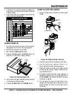
Page 46: ...3 kPa NOTICE If the engine is operating in very dusty or dry grass conditions a clogged air cleaner will result This can lead to a loss of power excessive carbon buildup in the combustion chamber and high fuel consumption Change air cleaner more frequently if these conditions exist Primary and Secondary Air Cleaner Elements 1 Release the latches Figure 60 that secures the cover to the air cleaner ...

Page 47: ...ly Ifthefuelfilter Figure61 has collected a significant amount of water and sediment at the bottom of the cartridge it should be drained off immediately OPEN DRAIN CLOSE A B C FILTER BODY HEAD AIR BLEEDER PLUG DRAIN VALVE FUEL FILTER CARTRIDGE RETAINING RING MAINTENANCE FUEL FILTER ELEMENT REPLACEMENT 1 Use a filter wrench to remove the fuel filter cup Figure 62 from the fuel filter body Figure 62...

Page 48: ...e the fuel water separator cartridge Figure 59 from the cartridge body head Figure 64 Fuel Water Separator 2 Wipe the inside of the fuel water separator cartridge body head with a clean cloth to remove any foreign matter or debris that may have accumulated 3 Install new fuel water separator cartridge first by hand until it makes contact with the cartridge body head surface 4 Tighten fuel water car...

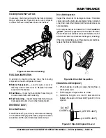
Page 49: ...ient charging of the battery adjust drive belt in accordance with the John Deere Operator s manual FUEL TANK MAINTENANCE Drive Belt Inspection Inspect the drive belt for damage and wear Horizontal cracks across the belt are acceptable Vertical direction of belt ribs cracks that intersect with horizontal cracks are not acceptable Also examine the belt and determine if it is oil soaked or glazed har...

Page 50: ...6 104 122 10 20 30 40 50 F C 5W 30 5W 40 10W 10W 30 10W 40 15W 40 20W 20 30 40 OIL SAE OIL DRAIN VALVE OPEN OIL DRAIN CAP REMOVE ENGINE OIL FILTER REPLACEMENT 1 Using an oil filter wrench Figure 69 remove engine oil filter Figure 69 Engine Oil Filter Removal 2 Clean the area around the lubricating oil filter head 3 Coat the rubber seal gasket surface of oil filter Figure 69 with clean 15W 40 engin...

Page 51: ...oolant temperature is below 120 F 50 C before removing pressure cap Heated coolant spray or steam can cause severe scalding and personal injury COOLANT DRAIN VALVE OPEN RADIATOR CLEANING The radiator Figure 71 should be sprayed cleaned with a high pressure washer when excessive amounts of dirt and debris have accumulated on the cooling fins or tube When using a high pressure washer stand at least ...

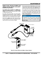
Page 52: ... using the generator in hot climates there is no need to apply power to jacket water heater heating element However if the generator will be used in cold climates it is best to apply power to the jacket water heater at all times If the generator will be used daily the battery should normally not require charging If the generator will be idle not used for long periods of time apply power to the bat...

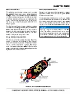
Page 53: ...ticles it oxidizes them This catalyst honeycomb like structure uses a chemical process to break down pollutants in the exhaust stream into less harmful components In general this catalyst collects burns accumulated particulates The DOC contains palladiumandplatinumwhichserveasacatalyststooxidize hydrocarbons and carbon monoxide EMISSION CARBON CHECK Deposition of carbon soot unburned fuel in the e...

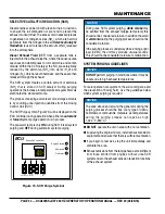
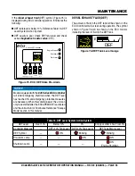
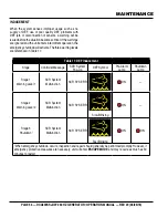
Page 54: ...ly ON during SCR forced system purging and OFF during automatic system purging Figure 74 SCR Purge Symbol Series 800 Controller ECU Engine Started Shutdown Pre Alarm Alarm Acknowledge Screen Change Program Exit Option SCR PURGE SYSTEM PURGING GUIDELINES For safe operation of equipment the surrounding area and the prevention of bodily harm use the guidelines below when system purging is required DO...

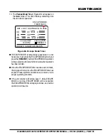
Page 55: ...on the ECU Controller main screen during operation The symbol shown in Figure 76 will be shown on the ECU monitor indicating the level of fluid in the DEF tank Figure 76 DEF Tank Level Guage DEF E F NOTICE Models equipped with the 845 Series ECU Controller will enter emergency shutdown when the DEF level has reached 0 and emergency protective measures are necessary When this condition exist the un...

Page 56: ...N 1 When emergency shutdown occurs inspection and repair should generally be performed promptly However if emergency protective measures are necessary unit will enter ESCAPE MODE and may require as much as 30 minutes to restart INDUCEMENT When the system senses improper usage such as no supply of DEF use of poor quality DEF problems with DEF jets or disconnection of sensors a warning will be issue...

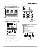
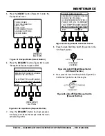
Page 57: ...Status Check Screen Diagnostic Mode 3 Next press the Program Exit button Figure 79 to enter the Main Menu UO VO WO UV VW U V WU KW KVA W ADD DEF OR USE ESCAPE MENU HZ 00000 9 h VOLTS AMPS DEF E F E F STATUS CHECK HOURS 00009 7 CANBUS IS WORKING OK EXIT 25 1v EXIT BUTTON DIAGNOSTIC MODE Figure 79 Main Screen 4 Press the DOWN button Figure 80 to scroll to the Escape Mode item Figure 80 Main Menu Dow...

Page 58: ...ANCED OPTIONS ESCAPE MODE UP DOWN SELECT REQUEST BUTTON ESCAPE MODE REQUEST EMERGENCY RESERVE ENGINE RUN MAY BE POSSIBLE TO ATTEMPT ESCAPE MODE PRESS THE REQUEST SOFT KEY EXIT REQUEST Figure 83 Escape Mode Activated Screen 8 Place the Auto Start Stop Switch Figure 84 to the Off Reset position Figure 84 Auto Off Reset Manual Switch Off Reset Position 9 Next place the Auto Start Stop Switch Figure 8...

Page 59: ...be available until around 30 minutes after operation has been ended Once the ESCAPE MODE timer reaches zero minutes the engine will stop since the ESCAPE MODE time has expired Please perform maintenance to return unit to proper operating condition If the unit returns to Warning Level 1 while ESCAPE MODE is running ESCAPE MODE will be cancelled the ESCAPE MODE timer display will close and normal op...

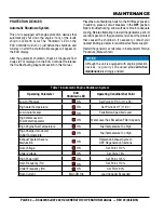
Page 60: ...aused the shutdown If necessary contact your nearest Multiquip dealer for additional technical support Restart the generator as reference in the Generator Startup Procedure Manual Start NOTICE Although the unit is equipped with engine protection devices regularly scheduled preventative maintenance is strongly advised Table 18 Automatic Engine Shutdown System Operating Parameter ECU Shutdown LED Op...

Page 61: ...CK BLUE BROWN GREEN GRAY VIOLET PINK R W Y LB LG O RED WHITE YELLOW LIGHT BLUE LIGHT GREEN ORANGE WIRE SIZE CODE WIRE COLOR 2 5 5 5 5 mm 2 8 8 mm NO MARK WIRE SIZE 1 25 Ar Fg ExAr ExFg AVR VR Re AS CB1 COT B OC CT 1 3 F MAIN GENERATOR ARMATURE WINDING MAIN GENERATOR FIELD WINDING EXCITER ARMATURE WINDING EXCITER FIELD WINDING RECTIFIER AUTOMATIC VOLTAGE REGULATOR VOLTAGE REGULATOR RHEOSTAT CURRENT...

Page 62: ...PAGE 62 DCA300SSJU4F2 60 HZ GENERATOR OPERATION MANUAL REV 0 06 26 18 ENGINE WIRING DIAGRAM ECU 845 ...

Page 63: ...DCA300SSJU4F2 60 HZ GENERATOR OPERATION MANUAL REV 0 06 26 18 PAGE 63 ENGINE WIRING DIAGRAM BASLER DGC2020HD OPTION ...

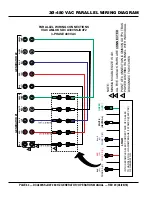
Page 64: ...E A U PHASE B V PHASE C W GENERATOR 2 BLK L1 RED L2 BLUE L3 WHITE NEU GREEN GND 3 MINIMUM CABLE SIZE IS 4 0 NOTE 1 ALL FIVE CAMLOK PAIRS ARE CONNECTED 2 POINT OF CONNECTION COMMON OUTPUT BUS POWER DISTRIBUTION PANEL WITH INDIVIDUAL DISCONNECT SWITCHES 3 LOAD IN THIS EXAMPLE SELECT CORRECT SIZE OF CABLES TO HANDLE FULL LOAD AMPERAGE 722 AMPS 480 VAC OF GENERATOR RED L2 PHASE B V BLUE L3 PHASE C W W...

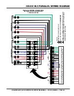
Page 65: ... C W GENERATOR 2 RED L2 WHITE NEU GREEN GND BLK L1 RED L2 BLUE L3 WHITE NEU GREEN GND 3 MINIMUM CABLE SIZE IS 4 0 NOTE 1 ALL FIVE CAMLOK PAIRS ARE CONNECTED 2 POINT OF CONNECTION COMMON OUTPUT BUS POWER DISTRIBUTION PANEL WITH INDIVIDUAL DISCONNECT SWITCHES 3 LOAD IN THIS EXAMPLE SELECT CORRECT SIZE OF CABLES TO HANDLE FULL LOAD AMPERAGE 1600 AMPS 208 VAC OF GENERATOR PHASE A U RED L2 PHASE B V BL...

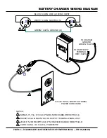
Page 66: ...6 AWG NEMA 5 15 15A 120 VAC P N HBL5278C HUBBLE RECEPTACLE NOTES 1 2 RECEPTACLE IS MOUNTED ON OUTPUT TERMINAL PANEL ASSY 20 AMP 5 20R RECEPTACLE P N HBL5369C HUBBLE RECEPTACLE 3 4 CORD CAROL 3 C 14 AWG P N EE56557 120 VAC INPUT INSERT EXTERNAL POWER CORD HERE 3 4 BLACK 14 AWG LINE L 120VAC INPUT WHITE 14 AWG NEUTRAL N GREEN 14 AWG GROUND G 1 2 3 4 B A B A 1 2 ...

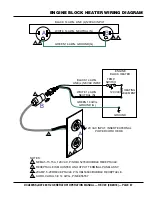
Page 67: ...8C HUBBLE RECEPTACLE BLACK 14 AWG LINE L 120VAC INPUT WHITE 14 AWG NEUTRAL N GREEN 14 AWG GROUND G NOTES 1 2 RECEPTACLE IS MOUNTED ON OUTPUT TERMINAL PANEL ASSY 20 AMP 5 20R RECEPTACLE P N HBL5369C HUBBLE RECEPTACLE 3 4 CORD CAROL 3 C 14 AWG P N EE56557 3 4 BLACK 14 AWG LINE L 120VAC INPUT WHITE 14 AWG NEUTRAL N GREEN 14 AWG GROUND G 1 2 3 4 B A B 120 VAC INPUT INSERT EXTERNAL POWER CORD HERE A 1 ...

Page 68: ...s wiring connection loose Check wiring and repair Is AVR defective Replace if necessary Defective Rotating Rectifier Check and replace Defective Exciter Field Check for approximately 19 ohms across J K on CN1 Low Voltage Output Is engine speed correct Place engine speed switch in High position Is wiring connections loose Check wiring and repair Defective AVR Replace if necessary High Voltage Outpu...

Page 69: ...ngine oil too thick Refill engine crankcase with correct type of oil for winter environment Defective battery Replace battery Engine fires but stops soon as starter is switched off Fuel filter blocked Replace fuel filter Fuel supply blocked Check the entire fuel system Defective fuel pump Replace fuel pump Engine stops by itself during normal operation Fuel tank empty Add fuel Fuel filter blocked ...

Page 70: ...ngine manual Engine overheats Too much oil in engine crankcase Drain off engine oil down to uppermark on dipstick Entire cooling air system contaminated blocked Clean cooling air system and cooling fin areas Fan belt broken or elongated Change belt or adjust belt tension Coolant insufficient Replenish coolant Radiator net or radiator fin clogged with dust Clean net or fin carefully Fan radiator or...

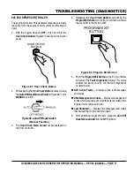
Page 71: ...ll be displayed on the ECU controller HOUR CHECK BUTTON 4 Releasing the Hour Check Button and pushing the Program Exit Button on the ECU controller will return the controller to the main screen Figure 89 Program Exit Button 5 Push the Program Exit Button on the ECU controller and select the Fault Diagnostics mode This mode enables the ability to carry out the fault diagnostics as listed below DM1 ...

Page 72: ...ns 2 Listen for an audiable click inside the control panel which is the run relay that controls the key switch 3 While in diagnostic mode the controller can see real time engine CAN Bus data including Diagnostic Trouble Codes DTC 4 To view active DTC codes navigate to Metering J1939 ECU DTC Active Data 5 ForpreviouslyactivecodesnavigatetoMetering J1939 ECU DTC Prev Data 6 Real time ECM parameters ...

Page 73: ...DCA300SSJU4F2 60 HZ GENERATOR OPERATION MANUAL REV 0 06 26 18 PAGE 73 NOTES ...

Page 74: ... co uk Tel 0161 339 2223 Fax 0161 339 3226 COPYRIGHT 2018 MULTIQUIP INC Multiquip Inc the MQ logo and the MQ Power logo are registered trademarks of Multiquip Inc and may not be used reproduced or altered without written permission All other trademarks are the property of their respective owners and used with permission This manual MUST accompany the equipment at all times This manual is considere...

Reviews: