MPS EVKT-5416 User Manual Download Page 7

User Guide 

MP5416 Evaluation Kit (EVKT-5416)


MP5416 Evaluation Kit User Guide Rev 1.31 

MonolithicPower.com


6


10/14/2019 

MPS Proprietary Information. Patent Protected. Unauthorized Photocopy and Duplication Prohibited. 


© 2019 MPS. All Rights Reserved. 


Section 3. Evaluation Kit Test Set-up 

3.1 Hardware Set-Up 

The hardware must be properly configured prior to use. Follow the instructions below to set up the EVB. 

1.  Locate the proper wires to connect the EVB to the EVKT-USBI2C-02 communication interface device. 
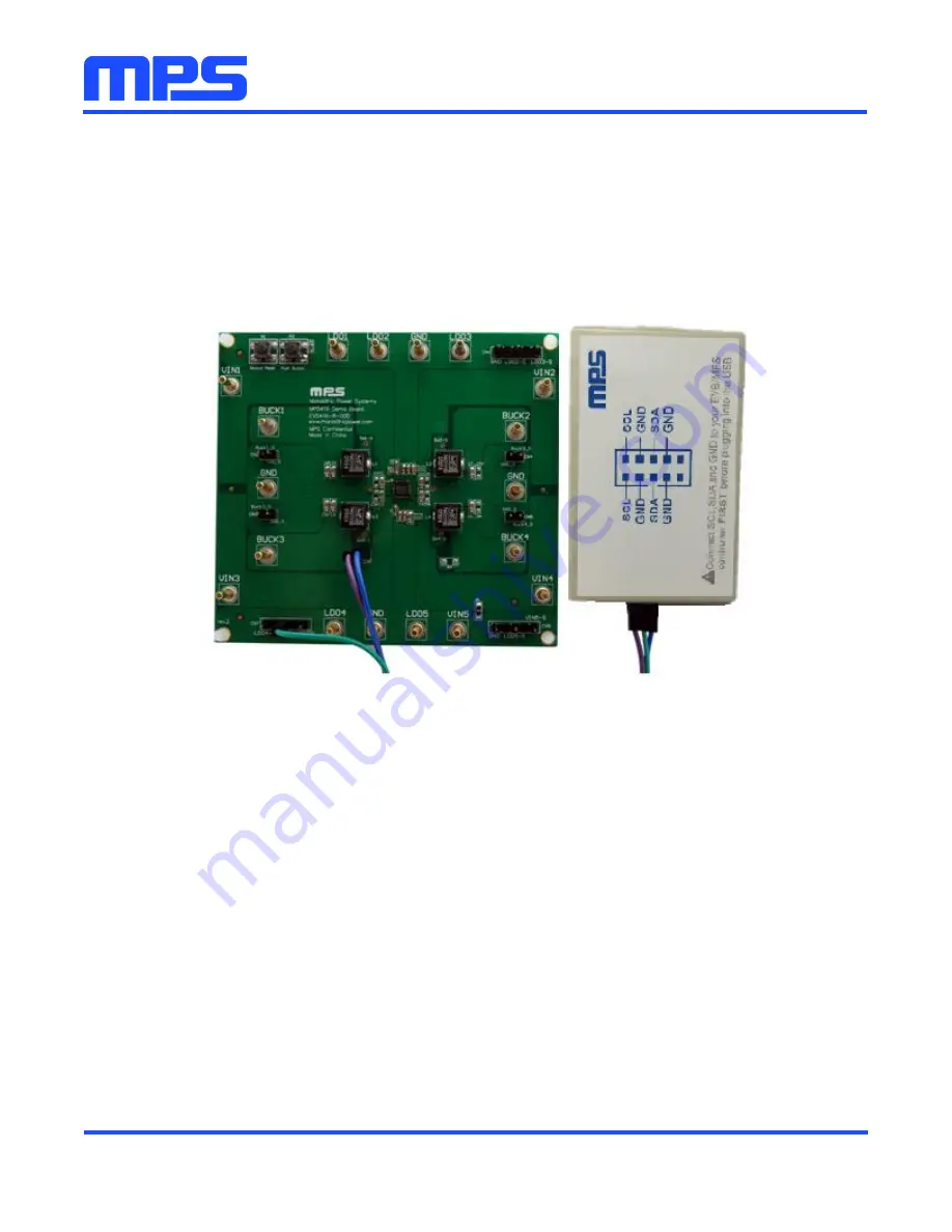
2.  Connect SCL, SDA, and GND (see Figure 6). If needed, refer to the datasheet for further clarification. 
3.  Use the USB cable to connect the EVKT-USBI2C-02 communication interface device to the PC and 

follow the instructions below to set up the EVB. 


Figure 6: EVB to MPS I

2

C Communication Interface Device Wire Connection


3.2 Powering up the EVB 

1.  Connect the positive and negative terminals of the load to the VOUT and GND pins, respectively. 
2.  Preset the power supply output between 3.5V and 5V, then turn off the power supply. 
3.  Connect the positive and negative terminals of the power supply output to the VIN and GND pins, 

respectively. 

4.  Turn the power supply on. 
5.  Press the P1 button on the EVB. The PMIC will enter the power on sequence automatically. 

3.3 Software Set-Up 

After connecting the hardware according to steps above, follow the steps below to use the GUI software. 

1.  Start the software. It will automatically check the EVB connection.  


If connection is successful, the address will be listed in the “Slave Address” (see Figure 7). 

Summary of Contents for EVKT-5416

Page 1: ...User Guide MP5416 Evaluation Kit EVKT 5416...

Page 2: ...tents 2 Features and Benefits 2 Kit Specifications 3 Section 1 Hardware Specifications 4 1 1 Personal Computer Requirements 4 1 2 EV5416 R 00D Specifications 4 1 3 EVKT USBI2C 02 Specifications 4 Sect...

Page 3: ...lows for quick evaluation of the PMIC and offers one time programming OTP capabilities which allows users to program custom configurations supporting a wide range of designs Kit Contents EVKT 5416 Kit...

Page 4: ...are outlined below I2C OTP Current limit of buck 2 and 4 Slew rate DVS Slew rate Discharge DISCHG System enable SYSEN Software reset SFRST Read status and ID2 registers Current limit of buck 1 and 3 S...

Page 5: ...EV5416 R 00D is an evaluation board for the MP5416GR CCCC For more information please refer to the EV5416 R 00D datasheet Figure 2 EV5416 R 00D Evaluation Board 1 3 EVKT USBI2C 02 Specifications The E...

Page 6: ...the software Note Note This software can be downloaded directly from the MPS website 1 Visit the MP5416 I2C GUI page at https www monolithicpower com en mp5416 i2c gui with otp html 2 Click the Downlo...

Page 7: ...interface device to the PC and follow the instructions below to set up the EVB Figure 6 EVB to MPS I2 C Communication Interface Device Wire Connection 3 2 Powering up the EVB 1 Connect the positive a...

Page 8: ...ure 7 Appearance of Address Shows Successful Connection If not one of two warnings will appear at the bottom 1 No Slave Found Please Check the Connection This means that the evaluation board is not co...

Page 9: ...evice is Not Connected 2 If connection is successful proceed to Step 3 Otherwise check connections between the EVB communication interface device and PC Re plug the USB into the computer and restart t...

Page 10: ...0 s and 1 s All changes made via the I2C will be restored to default values once the EVB is powered down 3 4 Device Programming Instructions The MP5416 CCCC can be custom programmed Follow the instru...

Page 11: ...igure 13 You can change any parameters listed Figure 13 Parameters that can be Adjusted in OTP Mode 7 Select values from the drop down menus Note that the WRITE and EXPORT buttons are active only when...

Page 12: ...ll Rights Reserved Figure 15 Various Locations Available to Export To 9 Wait for a status screen see Figure 16 Figure 16 Status Screen Indicates Success 10 Rename the file if you would like to refer t...

Page 13: ...ll Rights Reserved 12 Click the WRITE button A window should pop up see Figure 17 Figure 17 Important Warning User Must Increase Voltage 13 Increase the input voltage to a value between 6 2V and 6 5V...

Page 14: ...u try to perform OTP on a previously programmed device the GUI software will allow you to proceed normally However your configurations will NOT be saved 3 5 Troubleshooting Tips Note USBI2C 02 and USB...

Page 15: ...tion circuit If the input voltage AVIN is lower than the UVLO rising threshold the PMIC s functions are disabled Shutdown Event If the PMIC detects that the input voltage is lower than the UVLO fallin...

Page 16: ...onents of the evaluation kit can be purchased separately depending on user needs Part Number Description EVKT 5416 Complete evaluation kit Contents of EVKT 5416 EV5416 R 00D EV5416 evaluation board al...

Reviews: