


1 3
High-Tech Made in Switzerland
MCDISK-E
3.3 SET-UP
This chapter provides the information required to configure
the MCDISK-E reader/writer. It describes the setting of the
SCSI ID and configuring the SCSI termination.
If you have any doubts on configuration, contact your
MCDISK-E supplier or an authorized dealer of your host
computer.
WARNING: Before you begin, review and observe
the safety precautions described at the beginning of
this manual to avoid personal injury or damage to
equipment.
3.3.1 SET-UP OVERVIEW
Set-up of MCDISK-E-5 is a step by step procedure:
1. Remove the drive from its packing.
2. Set the unit’s SCSI ID (see chapter 3.3.3).
3. Terminate the SCSI bus if required (see chapter 3.4).
4. Connect the unit to the host computer
5. Connect the AC power and switch the unit on.
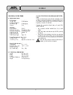
The default factory settings are as follows:
•
SCSI ID = 3
•
Parity disabled
•
Single SCSI ID
•
Full CIS mode
•
Termination enabled
•
Termpower enabled
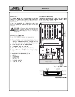
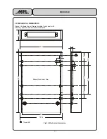
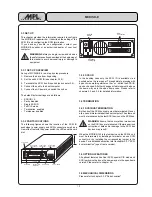
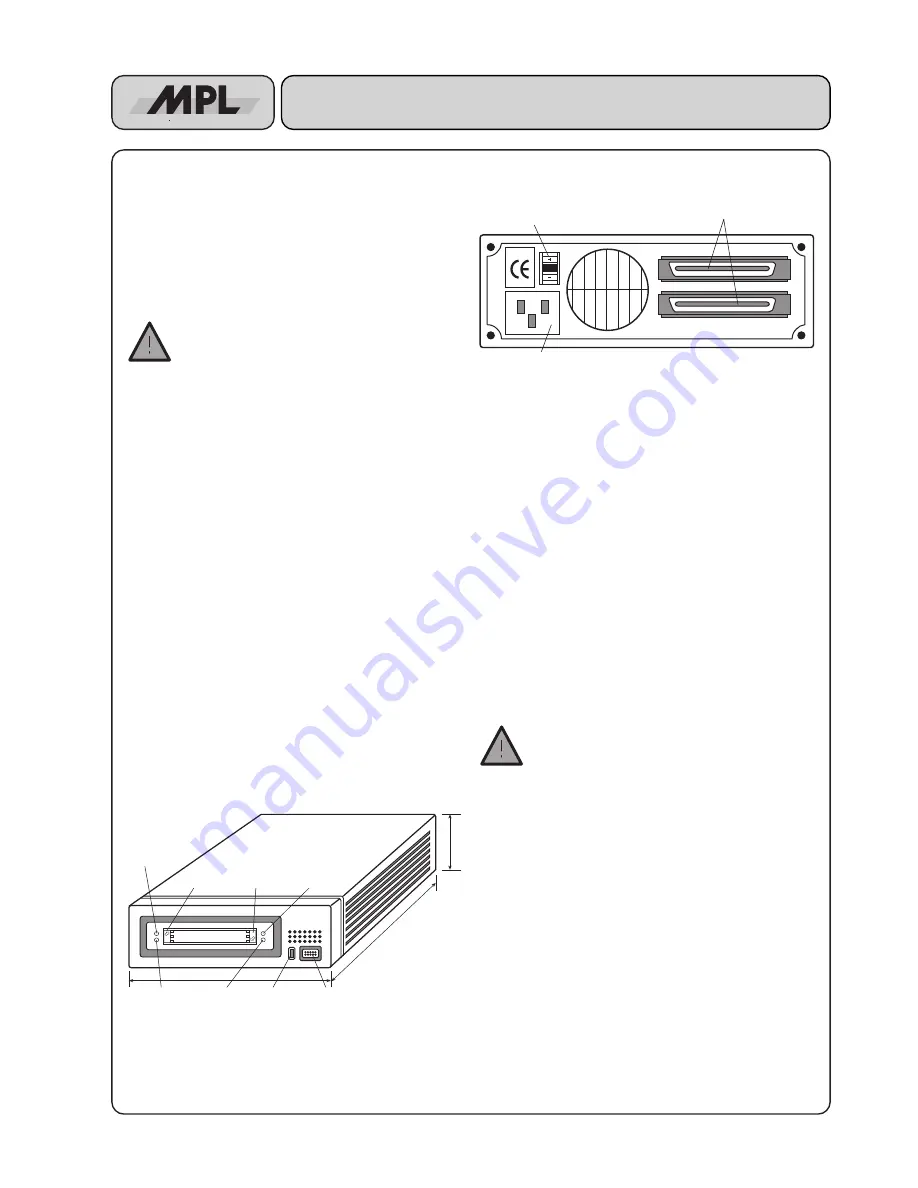
3.3.2 PARTS LOCATIONS
The following figures shows the location of the SCSI ID
pushwheel, power supply and SCSI connector as well as a
view of the front with the power switch, the LEDs and the card
slot.
56 mm
215 mm
170 mm
Upper card
eject button
Card slots
Error LED
Access LED
lower slot
Power LED
Power switch
Power LED
Access LED
upper slot
Lower card
eject button
90-264VAC
Power plug
SCSI ID
Switch
SCSI
Connectors
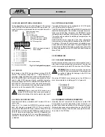
3.3.3 SCSI ID
In the desktop case only the SCSI ID is available via a
pushwheel on the rear panel. Through simple pressing with
a pencil or something similar on the + or - button the SCSI ID
can be changed. All other changes or features must be done
the same way as in the open frame case. Please refer to
chapters 2.3 and 2.4 for detailed information.
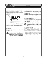
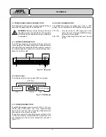
3.4 TERMINATION
3.4.1 SCSI BUS TERMINATION
Both ends of the SCSI bus cable must be terminated. Gener-
ally, one end is terminated at the host computer. The other end
must be terminated by the last SCSI device on the SCSI bus.
WARNING: Ensure that no more than two devices
on the SCSI bus are terminated. Otherwise serious
corruption of data and/or damage to the SCSI bus
devices may result!
When the MCDISK-G-5 is the last device on the SCSI bus, it
must be terminated by installing a terminator on one SCSI
connector or by installing the corresponding jumper in the
device. For a detailed description refer to chapter 2.5.1 "SCSI
bus termination" (open frame version).
3.5 OPTIONAL FEATURES
All optional features like Dual SCSI, special CIS mode and
SCSI parity must be done the same way as in the open frame
version. Please refer to chapter 2.4.
3.6 MECHANICAL DIMENSIONS
Please refer to chapter 3.3.2 "Parts Location" .