2 |
P a g e
Step 1 – Wiring
The following table shows you the necessary wires to connect from the
SP-402/502,
and what they connect to.
This chart only lays out what is needed for basic remote start operation and keyless entry. Any wires on your
remote start that are NOT listed in the table are NOT required. Security features are optional and connection
requirements will depend on your needs. For security connections, refer to
SP-402/502
owner’s manual and
your vehicle wiring chart.
SP402/502 Wire:
Connect to:
Found:
6-PIN HARNESS:
RED x2
Constant 12v (+)
Vehicle ignition harness
PINK
Ignition
Vehicle ignition harness
PINK/WHITE
*Ignition # 2*
(not present on all vehicles)
Vehicle ignition harness
BROWN
starter
Vehicle ignition harness
GRAY
Accessory
Vehicle ignition harness
12-PIN HARNESS:
RED/BLACK
Parking Light input wire (SEE NOTE 1)
Can connect to SP-402/502 red in 6-pin plug
WHITE
Parking Light output wire Typically @ fuse box/BCM, headlight switch,
or drivers kick panel.
BLACK
System Ground
(solid metal in vehicle)
GRAY
Hood pin (included) (SEE NOTE 2)
To prohibit the remote start from
activating while the hood is open.
Under hood
*This is an important safety feature!*
GREEN/RED
Vehicle trunk/back hatch release
This can be connected directly to (-) types
(refer to wire chart) *relay may be required*
See below for (+) and (+/-) relay diagrams
7-pin harness:
WHITE
Brake switch (+)
Above brake pedal
4-pin harness:
BLUE/BLACK
KEY-OVERRIDE-ALL (-) when running
Blue wire in 6-pin plug
3-PIN LOCK PLUG:
GREEN (-)
Vehicle lock wire
(refer to your vehicle wire chart)
BLUE (-)
Vehicle unlock wire
(refer to your vehicle wire chart)
The following MAY be needed:
ORANGE/BLACK
(12-pin harness)
Vehicle OEM Alarm Disarm wire
Use only if your vehicle has a factory
alarm system that gets tripped when you
attempt to activate the remote starter.
(refer to your vehicle wiring chart)
*Save connection for last to see if you need it*
NOTE 1
Some vehicles will call for a ‘+’ polarity connection to the parking light circuit and some will call for a ‘-
‘ connection. The red/black wire on the remote start is used to select the polarity of the remote start’s parking
light output. If your vehicle’s parking light wire is shown with a ‘+’ on your wiring chart, connect the red/black
wire to a co12v power source (you can tap it right on to one of the large red power input wires on the
remote start’s 6-pin harness). If your vehicle’s parking light wire is shown with a ‘-’ on your wiring chart,
connect the red/black wire to ground. The white wire in the remote start 12-pin harness is the actual parking
light output wire. After you’ve properly selected it’s polarity using the red/black wire, connect the white wire
to the parking light wire in your vehicle, as indicated on your wiring chart.
NOTE 2
The grey wire is used with a pin switch (included in your kit) to prohibit the remote start from activating
while the hood is open. This is an important safety feature!
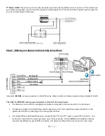
-Before proceeding, plug the antenna, programming button, and LED into the remote start. For tips on where
to install these, see Installer’s Tip #1 .


