MPC F1950i User Manual Download Page 20

MPC Computers 2005 ©     MAS001985-00 

20 


Preparing to Install a Wall-Mounting Arm 

To prepare to install a wall-mounting arm, complete the following steps: 

If the monitor is currently in use, turn it off and disconnect the power cord 
and video cable. 

Lower the display and re-insert the spring retention pin. (See white arrow 
in Figure 6.) 

Pull the screw cover off the back of the monitor if it is in place. 

Carefully place monitor face down on a flat padded surface. 

Support the base and remove the screws. (See black arrows in Figure 6.) 

Remove the base and pedestal. 

Follow the manufacturer's instructions to assemble the wall-mounting 
arm.  

Installing a Wall-Mounting Arm  

To install the wall-mounting arm, complete the following steps: 

Place the wall-mounting arm or mounting plate onto the back of the 
monitor. Line up the holes of the arm or plate with the holes in the back of 
the monitor. 


Insert the four screws into the holes and tighten. (See black arrows in 
Figure 6.) Be careful not to overtighten the screws. 

Attach arm to mounting plate, if required.  

Insert the power cable into the slot on the back of the monitor and 
reconnect the video cable. 


APPENDIX C — ON-SCREEN MESSAGES 

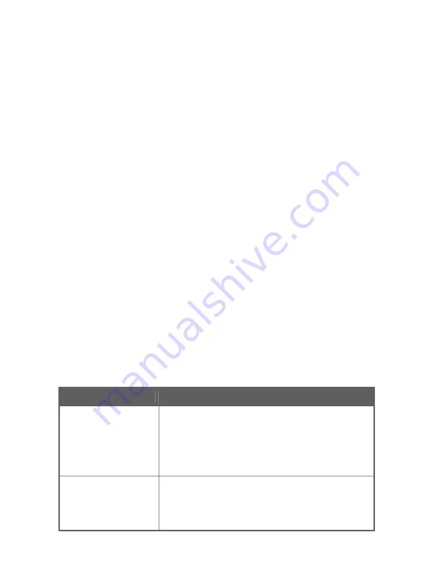
Table 5: On-Screen Messages 

Message 

Action 

No Signal 


Check that the signal cable is properly 
connected. If the connector is loose, tighten 
the connector screws. 


Check the DB-15 plug on the video cable for 
bent pins or other damage. 

Input Not Supported 


Your system may be set outside the display 
mode range of the monitor. Verify you are 
using a compatible display mode. (See Table 
6: Factory Preset Timing.)  

Summary of Contents for F1950i

Page 1: ...F1950i LCD Monitor User s Guide ...

Page 2: ...neral Instructions 10 Front Panel Controls 10 Accessing the Adjustment Controls 11 Adjusting the Picture 12 Monitor Drivers 15 Technical Support 15 Features 16 Energy Star Standards 16 Plug and Play DDC1 2B Feature 16 Appendix A Troubleshooting 17 Appendix B VESA Mounting 19 Attaching an Optional Wall Mounting Arm 19 Appendix C On Screen Messages 20 Appendix D Factory Preset Timing 21 Appendix E C...

Page 3: ...pping carton and packing materials to transport or ship your monitor If you transport the monitor over long distances completely repackage the monitor in its original packing material SAFETY INFORMATION Do not use the monitor near standing bodies of water or in humid envirionments Set the monitor on a flat stable surface Do not place it on an unstable cart stand or table If the monitor falls it mi...

Page 4: ...sion cords can result in a fire or electric shock Never push objects of any kind into the monitor through openings The objects could touch dangerous voltage points or short out parts possibly resulting in an electric shock or a fire hazard Never spill liquid of any kind on the monitor If this occurs disconnect from the power source immediately Do not attempt to service the monitor yourself Opening...

Page 5: ... after image or ghost of the previous image may remain after switching the image when the same image is displayed for a long time In this case you can recover the screen slowly by changing the image or turning off the monitor for a few hours The life of the internal fluorescent backlights used in the LCD monitor is approximately 30 000 hours Contact MPC Technical Support or an authorized dealer fo...

Page 6: ...r is upright because this may damage the monitor Monitor Base INSTALLING BASE To install the monitor base place the base on a firm flat surface and insert the monitor pedestal into the base 2 until it snaps into place After the pedestal is firmly seated in the base remove spring retention pin 1 to allow height adjustments DO NOT DISCARD the spring retention pin It may be needed for relocation or b...

Page 7: ...lines below This monitor has an integrated universal power supply It can operate in either a 100 120 VAC or 220 240 VAC voltage area No user adjustment is required Make sure the power cord meets the specifications and requirements for your area The power cord included with your monitor is rated for 100 120 VAC Caution If the AC outlet is not grounded with three holes install the proper grounding a...

Page 8: ...rt taking care not to bend any pins on the connector 2 Plug the other end of the video cable into the appropriate Video VGA or DVI connection on the monitor See 2 and 3 in Figure 2 taking care not to bend any pins on the connector 3 Tighten the two screws on each end of the video cable with your fingers to secure the connection Caution Over tightening this connection can damage the monitor cable o...

Page 9: ... 9 Figure 3 Adjusting the viewing position Caution Do not touch the LCD screen when you change the position or the screen may become damaged or broken Warning Be careful not to pinch your fingers when adjusting the monitor s position ...

Page 10: ...y to the monitor and to your computer s video port 3 Locate and press the power button The power indicator will light up The monitor features a unique quick switch system A picture should appear within seconds after the monitor is turned on See Figure 4 and Table 1 Front Panel Controls The Power button is located on the front panel of the monitor The buttons to the left and right of the Power butt...

Page 11: ...ow power mode low power consumption no picture 4 Contrast Press this button to adjust the display contrast If the OSD is open this button will move through the selections in the OSD After a selection is made in the OSD this button will increase the value of the selection 5 Menu Enter Press this button to open the OSD menu or to select an adjustment icon within the OSD Accessing the Adjustment Cont...

Page 12: ...below describes the functional control icons that appear on the Level 1 OSD menu Table 2 Functional Control Icons Function Icon Description Luminance Use this to enter the Luminance control Contrast and Brightness are adjustable in this section Image Setup Use this to enter the Image Setup control Focus and Clock are adjustable in this section Image Position Use this to enter the Image Position co...

Page 13: ...eout is adjustable here Language Use this function to select which language the monitor will use to display the instructions Information Use this function to view the current display resolution and frequency Reset Use this function to clear each old status of auto configuration and to redo auto configuration Exit Use this feature to save your selections and adjustments and to exit the OSD menu Adj...

Page 14: ...on Use this function to adjust the picture s vertical position Disabled when using Digital input Color Adjustment Cool Preset Use this option to set the color to a cool white setting that is better for viewing text This setting has less RED than the WARM setting Color Adjustment Warm Preset Use this option to set the color to a warm white setting This setting has more RED than the COOL setting and...

Page 15: ...ou do not have Internet access you may also call MPC Technical Support at 800 877 8856 to request that the files be sent to you TECHNICAL SUPPORT In the unlikely event that you have a failure with your MPC monitor you can contact MPC Technical Support at http support mpccorp com If you do not have Internet access you may also call MPC Technical Support at 800 877 8856 Technical Support will provid...

Page 16: ...ption After the video input signal is restored full power is restored and the display is automatically redrawn The appearance is similar to a Screen Saver feature except the display is completely off The display is restored by pressing any key on the keyboard or clicking the mouse Plug and Play DDC1 2B Feature This monitor is equipped with VESA DDC1 2B capabilities according to the VESA DDC STANDA...

Page 17: ...connected Verify the PC system is Plug and Play compatible Verify the video card is Plug and Play compatible Check the DB 15 plug on the video cable for bent pins The picture is fuzzy Adjust the Contrast and Brightness controls Initiate the automatic calibration function by pressing the Auto button The picture bounces or a wave pattern is present in the picture Initiate the automatic calibration f...

Page 18: ...he system s mouse and press several keys on the keyboard to wake the system Make sure the computer s video card is completely seated in the slot The screen image is not centered or sized properly Adjust pixel frequency Clock and Focus or press the Auto Config button Select the Auto Center function in the OSD to center the display The picture has poor brightness or contrast The lifetime of the back...

Page 19: ...nting arm which you purchase separately This monitor has a 100 mm x 100 mm VESA compliant mounting pad Use a wall mounting arm with a VESA compatible configuration only Figure 6 Installation of an Optional Wall Mounting Arm Caution Be careful when installing the wall mounting arm To avoid LCD damage make sure you properly support the monitor ...

Page 20: ... mounting arm complete the following steps 1 Place the wall mounting arm or mounting plate onto the back of the monitor Line up the holes of the arm or plate with the holes in the back of the monitor 2 Insert the four screws into the holes and tighten See black arrows in Figure 6 Be careful not to overtighten the screws 3 Attach arm to mounting plate if required 4 Insert the power cable into the s...

Page 21: ... Hz 640 x 400 31 469 kHz 70 Hz DOS 720 x 400 31 469 kHz 70 Hz 640 x 480 31 470 kHz 60 Hz 640 x 480 37 861 kHz 72 Hz VGA 640 x 480 37 500 kHz 75 Hz 800 x 600 37 879 kHz 60 Hz 800 x 600 48 077 kHz 72 Hz SVGA 800 x 600 46 875 kHz 75 Hz 1024 x 768 48 363 kHz 60 Hz 1024 x 768 56 476 kHz 70 Hz XGA 1024 x 768 60 023 kHz 75 Hz 1280 x 1024 63 981 kHz 60 Hz SXGA 1280 x 1024 79 976 kHz 75 Hz ...

Page 22: ...round 12 DDC Serial Data 5 Ground 13 H sync 6 R Ground 14 V sync 7 G Ground 15 DDC Serial Clock 8 B Ground Table 8 DVI Digital Video Cable Pin Assignments Pin Description Pin Description 1 TMDS RX2 13 Floating 2 TMDS RX2 14 5V Power 3 TMDS Ground 15 Ground 4 Floating 16 Hot Plug Detect 5 Floating 17 TMDS RX0 6 DDC Clock 18 TMDS RX0 7 DDC Data 19 TMDS Ground 8 Floating 20 Floating 9 TMDS RX1 21 Flo...

Page 23: ...m five black dots Maximum two joined adjacent black dots Minimum distance between two black dots 10mm No defects allowed with three adjacent black dots Total Dot Failures Maximum of eight dots including bright and dark dot defects APPENDIX G MONITOR SPECIFICATIONS Table 10 Monitor Specifications LCD Panel Type TFT Active Matrix Color LCD Size 19 0 in 48 3 cm Viewable size 19 0 in 48 3 cm Pixel pit...

Page 24: ...s 15 pin D Sub Analog 24 pin DVI Digital Input Video Signal Analog and Digital 0 7 Vp p standard 75 OHM Positive Power Source Integrated Power Supply AC Source 100 to 240 VAC 50 60 Hz Environmental Considerations Operating Temp 41 F to 95 F 5 C to 35 C Storage Temp 4 F to 140 F 20 C to 60 C Operating Humidity 10 to 85 Weight Shipping 19 8 lb 9 0 kg Display Only 15 5 lb 7 02 kg Display without base...

Page 25: ...he following methods 1 Reorient or relocate the receiving antenna 2 Increase the separation between the equipment and the receiver 3 Plug the equipment into an outlet on a different circuit than the receiver 4 Consult the dealer or an experienced radio TV technician for help Notice Any changes or modifications to the monitor not expressly approved by the party responsible for compliance could void...

Reviews: