


SMG-6100 Hardware
Introduction
Overview
The SMG-6100 is based on the Intel x86 processor and supports VGA, 4 Ethernet ports, 2 RS-232 serial ports,
and USB. It comes in a standard 19-inch, 1U high form factor with built-in IPSec, making it an ideal
communication platform for industrial machine-to-machine M2M applications.
The SMG-6100 can be used as a communication gateway with sophisticated M2M solutions to help construct a
tunnel server (IPSec) and bi-directional IP communications. When used with Moxa’s SMG-1100, the SMG-6100
can serve as a secure networking host over IPSec to back-end host computers and Modbus TCP Master/Slave
devices. One of the key benefits in this architecture is to facilitate and accelerate the remote monitoring and
management of Modbus devices.
Package Checklist
Before installing the SMG-6100, verify that the package contains the following items:
•
1 SMG-6100 gateway
•
Ethernet cable: RJ45 to RJ45 cross-over cable, 100 cm
•
Power cord
•
Documentation and software CD
•
Quick installation guide (printed)
•
Warranty card
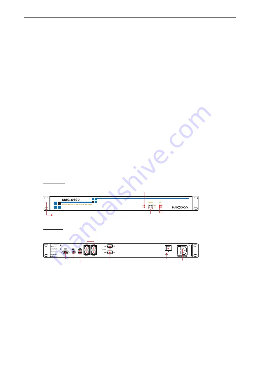
Appearance
Front View
LED Indicators (TX, RX)
19-inch
Rackmount Ear
LED Indicators
(Power, Storage)
LED Indicators
(10/100 Mbps)
Rear View
10/100 Mbps
Ethernet x 4
RS-232
Serial Port x 2, DB9
Reset Button
VGA PS/2
USB 2.0
Host x 2
Power Input
Power Switch
1-2


