


SMG-6100 Hardware
Hardware Installation
Wiring Requirements
The following common safety precautions should be observed before installing any electronic device:
•
Use separate paths to route wiring for power and devices. If power wiring and device wiring paths must
cross, make sure the wires are perpendicular at the intersection point.
•
You can use the type of signal transmitted through a wire to determine which wires should be kept separate.
The rule of thumb is that wiring that shares similar electrical characteristics can be bundled together.
•
Keep input wiring and output wiring separate.
•
When necessary, it is strongly advised that you label wiring to all devices in the system.
ATTENTION
Do not run signal or communication wiring and power wiring in the same wire conduit. To avoid interference,
wires with different signal characteristics should be routed separately.
ATTENTION
Safety First!
Be sure to disconnect the power cord before installing and/or wiring your device.
Electrical Current Caution!
Calculate the maximum possible current in each power wire and common wire. Observe all electrical codes
dictating the maximum current allowable for each wire size.
If the current goes above the maximum ratings, the wiring could overheat, causing serious damage to your
equipment.
Temperature Caution!
Be careful when handling the unit. When the unit is plugged in, the internal components generate heat, and
consequently the outer casing may feel hot to the touch.
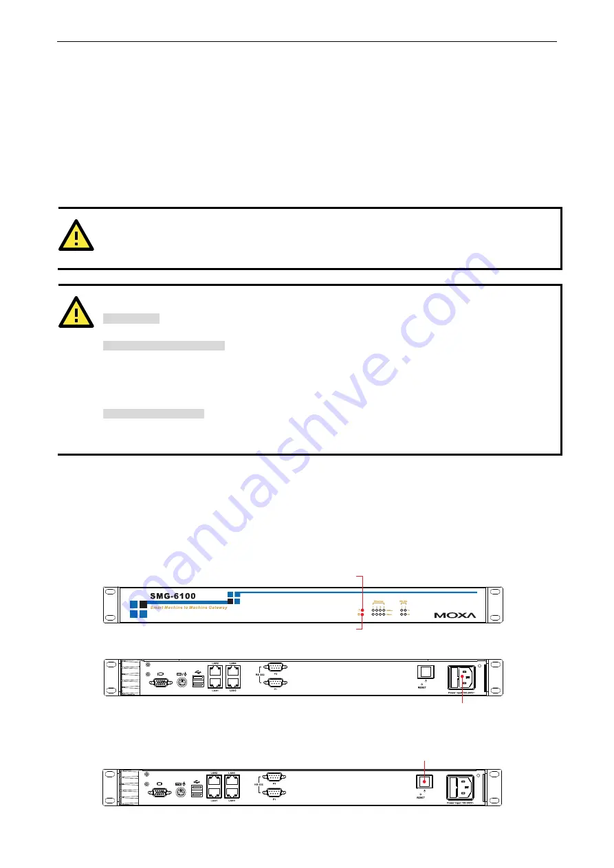
Connecting the Power
To power on the SMG-6100 connect the power line to the SMG-6100’s AC power connector (located on the right
side of the rear panel) using the power cord shipped with the product, and then turn on the power switch. If the
power is properly supplied, the Power LED will light up first, and then the Storage LED will start blinking. It
takes about 30 to 60 seconds for the operating system to boot up.
Power Input
Power LED
Storage LED
If you find the computer has not been powered on, press the Power Switch to start the system.
Power Switch
2-4


