MC-3201 Series Hardware User Manual
15
Connecting to a Network
To connect the MC-3201 computer to a network, connect a network cable to the computer’s Ethernet port
and connect the other end of the cable to your Ethernet network. When the cable is properly connected, the
LEDs on the computer’s Ethernet port turn on to indicate a valid connection.
Four 10/100/1000 Mbps Ethernet ports with RJ45 connectors are located on the rear panel of the computer.
NOTE
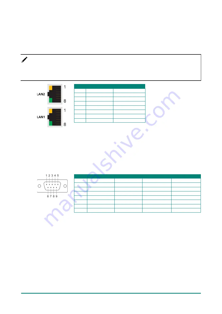
The pin assignments for the MC-3201 computer’s Ethernet port are shown in the following figure. If you
want to use your own Ethernet cable, ensure that you match the pin assignments of the connector on the
Ethernet cable.
Pin
10/100 Mbps
1000 Mbps
1
ETx+
TRD(0)+
2
ETx-
TRD(0)-
3
ERx+
TRD(1)+
4
–
TRD(2)+
5
–
TRD(2)-
6
ERx-
TRD(1)-
7
–
TRD(3)+
8
–
TRD(3)-
Connecting to a Serial Device
Use a serial cable to connect your serial device to the computer’s serial port. The serial ports P1 to P2 have
male DB9 connectors and can be configured for RS-232, RS-422, or RS-485 communication. For information
on serial port configuration, refer to the MC-3201 software manual.
The pin assignments of the serial ports are shown in the following table:
DB9 Male Port
RS-232/422/485 Pinouts
Pin
RS-232
RS-422
RS-485 (4-wire) RS-485 (2-wire)
1
DCD
TxDA(-)
TxDA(-)
–
2
RxD
TxDB(+)
TxDB(+)
–
3
TxD
RxDB(+)
RxDB(+)
DataB(+)
4
DTR
RxDA(-)
RxDA(-)
DataA(-)
5
GND
GND
GND
GND
6
DSR
–
–
–
7
RTS
–
–
–
8
CTS
–
–
–
Connecting to a USB Device
The MC-3201 is provided with two USB 3.0 ports with type-A connectors on the front panel, and four USB
2.0 ports on the rear panel. These ports can be used to connect to an external flash disk or hard drive. You
can also use these USB ports to connect to a keyboard or a mouse.
Connecting to a Display Port
The MC-3201 Series offers two display ports located on the rear panel, allowing users to connect to a video
device. Make sure you use a certified cable for a reliable video connection.


