background image


D


D.


Used Network Port Numbers 

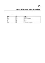
ioPAC 8020 Network Port Usage 

Port 

Type 

Usage 

80 

TCP 

Web Server 

502 

TCP 

Modbus Communication 

161 

TCP 

SNMP   

68 

UDP 

BOOTPC 

68 

UDP 

DHCP 

4800 

UDP 

Auto search(handled by MOS) 


Summary of Contents for ioPAC 8020

Page 1: ...ioPAC 8020 Modular RTU Controller User s Manual First Edition September 2010 www moxa com product 2010 Moxa Inc All rights reserved Reproduction without permission is prohibited ...

Page 2: ...se Moxa reserves the right to make improvements and or changes to this manual or to the products and or the programs described in this manual at any time Information provided in this manual is intended to be accurate and reliable However Moxa assumes no responsibility for its use or for any infringements on the rights of third parties that may result from its use This product might include uninten...

Page 3: ...e Built in Web Console 4 1 Overview for ioPAC 8020 4 2 Entering the Web Console 4 2 Overview 4 3 Basic Settings 4 3 Network Settings 4 3 5 Click Go Introduction 5 1 Overview 5 2 Features 5 3 Click Go Logic Basics 5 3 Working with Rules 5 4 Developing Your Logic Rules 5 4 Define Global Variables 5 5 Internal Register Settings 5 5 Timer Settings 5 6 SNMP Trap Server 5 6 E Mail Server 5 7 Active Mess...

Page 4: ...F Factory Default Settings F 1 ...

Page 5: ...t swappable I O modules can connect to various sensors and on off switches for automation applications and the CPU module provides local intelligence that can communicate over Ethernet and IP based networks The following topics are covered in this chapter ioPAC 8020 Modular RTU Controller Product Features Package Checklist Available Products Product Specifications Physical Dimensions Hardware Refe...

Page 6: ...s simple logic control and powers the whole system Each CPU module is equipped with five I O slots for different I O modules The last module slot can be filled by a backup power module or an additional I O module Product Features Robust and Compact Design for Harsh Environments 40 to 75 C operating temperature range Anti vibration spring lock terminal block All aluminum chassis design Two LAN port...

Page 7: ...ive Messages The ioPAC 8020 controller is an entry level controller with its own private programming language called Click Go Click Go has 80 event based logic rules built in to give your ioPAC 8020 the intelligence needed to control a wide range of applications All alarm messages support Unicode text Built in Web Console The ioPAC modular RTU controller includes a built in web console You can mon...

Page 8: ...nalog inputs 0 to 10 V 40 to 75 C operating temperature Product Specifications Computer CPU ARM9 based CPU 32 bit 160 Mhz SDRAM 8 MB Flash 4 MB I O Scan Time 100ms Program Cycle Time 100ms Ethernet Interface LAN 2 auto sensing 10 100 Mbps ports M12 or RJ45 Ethernet Relay Function Hardware Normal Close Serial Interface Serial Standards RS 232 422 485 ports DB9 male Serial Signals RS 232 TxD RxD DTR...

Page 9: ... 61000 4 6 CS level 2 IEC 61000 4 8 PM level 1 IEC 61000 4 11 DIP IEC 61000 6 2 ESD level 2 3 IEC 61000 6 4 EFT level 2 Safety UL508 Pending Shock IEC 60068 2 27 Freefall IEC 60068 2 32 Vibration IEC 60068 2 6 Rail Traffic EN50155 Pending EN50121 3 2 Pending EN50121 4 Pending Note Please check Moxa s website for the most up to date certification status Warranty Warranty Period 2 years Details See ...

Page 10: ...ioPAC 8020 Rugged Remote I O Introduction 1 6 Physical Dimensions ...

Page 11: ...ADY LED turns green again You may then release the reset button LED Indicators for CPU Module Group Pins Description Printed label Ethernet On the Plug Ready Green Power On System working Normally Green Flashing Click Go Active Interlaced Green Red Flashing Safe Mode Red System Error Ready I O Off I O Module does not exist Green Connecting I O Module and working normally Green Flashing Communicati...

Page 12: ... Each DIO or AIO module is equipped with a Module Status LED indicating operation status LED Name LED Color LED Function Status Off Not powered or Unknown Module Green Steady On System ready Flashing I O module is in communication Red Steady On I O module isn t in configuration ...

Page 13: ...PAC 8020 and its I O Modules The following topics are covered in this chapter Installing the ioPAC on a DIN Rail Removing the ioPAC from the DIN Rail Grounding the ioPAC System Inserting Removing I O Modules from the ioPAC Connecting the Power System Connecting to the Network ...

Page 14: ...ed I O modules When the total current consumption of the I O modules exceeds 1 5A you will need to insert an extra power module Installing the ioPAC on a DIN Rail The aluminum DIN Rail attachment plate should already be fixed to the back panel of the ioPAC 8020 when you take it out of the box If you need to reattach the DIN Rail attachment plate to the ioPAC 8020 be sure the spring loaded bracket ...

Page 15: ...shown in the diagram to the right Next rotate the bottom of the switch upwards and then remove the switch from the DIN Rail Grounding the ioPAC System The ioPAC 8020 is grounded to enhance EMS performance The ioPAC 8020 comes with metal DIN Rail brackets for grounding the system For optimal EMS performance connect the chassis ground nut on the ioPAC 8020 to the grounding point The ground nut is lo...

Page 16: ...ernet There are two LAN ports both of which use the same MAC address located on the device s front panel These two LAN ports are used to connect to Ethernet enabled devices Most users will choose to configure these ports for Auto MDI MDI X mode in which case the port s pinouts are adjusted automatically depending on the type of Ethernet cable used straight through or cross over and the type of dev...

Page 17: ...below LAN Port Default IP Address Default Netmask Default Gateway Port 0 1 192 168 127 254 255 255 255 0 None There are two ways to configure the ioPAC 8020 One is to use Modular_ioAdmin the other is to use the web console Once the ioPAC 8020 has been detected modify the settings as needed for your network environment then restart the I O 3 1 Using Modular_ioAdmin Please refer to chapter 3 for det...

Page 18: ...hich allows you to configure monitor and edit Click Go TFTP The utility which allows you to mass deploy the configuration file The following topics are covered in this chapter Features of ioAdmin Modular ioAdmin Main Screen Main Screen Overview Functions on the Menu Bar Watchdog Tab Administrator Click Go Logic Tab Administrator SNMP Tab Administrator Using TFTP to Import Export Configuration ...

Page 19: ...olve any IP conflicts when you first install two or more ioPAC 8020s to the same network at the same time Remote Management Modular_ioAdmin allows users to find and configure multiple ioPAC 8020 systems over the Ethernet network and monitor and configure attached I O devices You can also test I O devices and reset the system Click Go Logic Editor Click Go is an event based front end intelligent lo...

Page 20: ... Start Search to find the I O system automatically or you can click Exit and then add the ioPAC 8020 system manually If two or more I O systems with the same IP address are found Modular_ioAdmin will ask you to modify the IP address in a pop up window and then reboot the I O system If multiple ioPAC 8020 units are installed on the same network remember that each unit has the same default IP addres...

Page 21: ...bar system Network Interface 2 The device is not in the same network segment as your host PC You can add them manually Click the Device tag in the Navigation Panel and then choose Add new device In the pop out window key in the IP address of the ioPAC you want to add Check the Ethernet cable if the methods above do not solve the problem Login as Administrator After the ioPAC 8020 is displayed in t...

Page 22: ... event 1 Continue This action will apply the currently detected I O module combination to the system All configurations of old module are preserved The removed I O modules will disappear and added modules will be applied with default settings The system does not clear any Click Go rules you have saved and you can still start it at your own risk 2 Restore order Recover to the previous module combin...

Page 23: ...ions are not available until you log in as an administrator 1 Modular ioAdmin Title 5 Quick Link 2 Menu Bar 6 Main Screen 3 Navigation Panel 7 Sync Rate Information 4 Status Bar Functions on the Menu Bar File From the File menu you can export the list of devices that are currently displayed in the navigation panel You also can import a list of devices into Modular_ioAdmin When exporting importing ...

Page 24: ...he unit is in 10 msec increments so if you enter 100 the refresh rate becomes 1 sec TCP Socket Timeout Interval allows you to select the preferred timeout value for TCP socket communication Active Message Listen Port specifies the port number to use for ioPAC 8020 messages If your network uses a firewall you can coordinate this setting with your firewall settings to ensure that active messages get...

Page 25: ... a remote site You will need to log in as an administrator to use this function Reset to Default Administrator Mode Required Use this command to reset all settings including console password to factory default values You will need to log in as an administrator to use this function Export Import System Config Administrator Mode Required Use this command to reload a configuration that was exported t...

Page 26: ... password has been set up simply click on Login and leave the Password for entry field blank Additional detail is provided later in this chapter Message Monitor Tab The Message Monitor tab will display any TCP UDP I O messages received from the ioPAC 8020 When you install the ioPAC 8020 for the first time the active I O messaging ruleset will not have been defined yet so there will be no messages ...

Page 27: ...e loss of all configuration settings and your Click Go Logic active I O messaging program When making configuration changes you will need to click on Update or on Apply to save the changes Some changes will require a restart of the ioPAC 8020 system in order to take effect and you will be given the option to restart the computer if necessary I O Configuration Tab Administrator When logged on as an...

Page 28: ...You can drag the border to enlarge or reduce the column width Config For output modules only The list in this tab displays the module safe mode settings such as Power On Disconnection and system failure You can double click to enter the setting After you double click the channel setting window will pop up It allows you to set the safe mode power on status test I O and assign an alias name ...

Page 29: ... two situations that will cause the ioPAC modular RTU controller to enter Safe Status One is if the Host connection is lost the other is if the internal I O bus fails When the ioPAC 8020 is in safe mode the user can not start Click Go logic and the user can not change the module configuration 1 Host Connection lost The I O LED will be lit steady Red The Host Connection Watchdog is disabled by defa...

Page 30: ...t originate from sources that are not listed in the accessible IP list will be unable to use Modbus TCP or Modular ioAdmin to access the ioPAC 8020 Modbus TCP Alive Check Timeout Settings The Modbus TCP Alive Check Timeout is designed to avoid TCP connection failure When the host is down the ioPAC 8020 will continue to wait for a response from the host This will cause the TCP port to be indefinite...

Page 31: ...dministrator Click the Watchdog tab to configure the conditions for entering Safe Mode While the ioPAC 8020 is in Safe Mode it will stop Click Go and force each output channel to keep its predefined Safe Status setting Once the system enters Safe Mode the LED indicator will blink red and green 1 Enable Host Connection Watchdog Check this option to see if the Modbus TCP connection is still alive If...

Page 32: ...over the network Please refer to Chapter 6 for more detailed information Changes made in the Click Go Logic tab are not effective until the ioPAC 8020 is restarted just like changes made in other tabs NOTE Note that when Click Go Logic is being used the range and units of I O channel being used in Click Go Logic may not be modified SNMP Tab Administrator The ioPAC supports SNMP V1 V2c and V3 Simpl...

Page 33: ...hown below You can use TFTP in a batch file to transfer configuration files for different units For example you might have two configuration files that need to be copied to two different servers ik8020_1 txt for 192 168 127 253 and ik8020_2 txt for 192 168 127 254 A batch file could be written as follows tftp 192 168 127 253 put ik8020_1 txt ik8020 txt tftp 192 168 127 254 put ik8020_2 txt ik8020 ...

Page 34: ...eb Console This chapter introduces built in web console when monitoring the ioPAC modular RTU controller system The following topics are covered in this chapter Entering the Web Console Overview Basic Settings Network Settings ...

Page 35: ...nel is the main window The window shows the contents of the currently selected page in the navigation panel For example if you click on Basic Settings in the navigation panel the main window will show a page of basic settings that you can configure You must click on the Submit button after making configuration changes The Submit button is always located at the bottom of every page that has configu...

Page 36: ...es and I O modules for the current system on one page Press F5 to refresh the page and update the I O status Basic Settings On the Basic Settings page you may set the ioPAC 8020 s system time or provide the IP address of a time server for time synchronization Network Settings General settings On the General Settings page you may assign a device name and location to assist you in differentiating be...

Page 37: ...t channel s Safe Status settings To enable the Watchdog check off Enable connection watchdog set the timeout value and restart the I O system With Watchdog enabled the ioPAC 8020 will enter Safe Status after there is disruption in communication that exceeds the time specified Ethernet Configuration On the Ethernet Configuration page you may set up a static or dynamic IP address for the ioPAC 8020 ...

Page 38: ...tmask Any host Disable 192 168 1 120 192 168 1 120 255 255 255 255 192 168 1 1 to 192 168 1 254 192 168 1 0 255 255 255 0 192 168 0 1 to 192 168 255 254 192 168 0 0 255 255 0 0 192 168 1 1 to 192 168 1 126 192 168 1 0 255 255 255 128 192 168 1 129 to 192 168 1 254 192 168 1 128 255 255 255 128 SNMP Agent On the SNMP Agent page you may enable SNMP and set the read and write community strings The io...

Page 39: ...iguration file can be generated by ioAdmin or through the web console This function can be used to duplicate settings between ioPAC 8020 systems You will be prompted for the location of the configuration file i e ik8020 txt Export System Config On the Export System Config page you may click the file name ik8020 txt to save the ioPAC s configuration into a file for backup or import into another ioP...

Page 40: ...TION If you forget the password the ONLY way to configure the ioPAC 8020 is by using the reset button to load the factory defaults Before you set a password for the first time it is a good idea to export the configuration to a file when you have finished setting up your ioPAC 8020 Your configuration can then be easily imported back into the ioPAC 8020 if you need to reset the ioPAC 8020 due to a f...

Page 41: ...it to develop your active I O messaging program The following topics are covered in this chapter Overview Features Click Go Logic Basics Working with Rules Developing Your Logic Rules Define Global Variables Internal Register Settings Timer Settings SNMP Trap Server E Mail Server Active Message Server IF THEN ELSE Statement IF Conditions THEN ELSE Actions Working with Click Go Rulesets Activating ...

Page 42: ...CP UDP message only when the switch attached to DI 0 is turned on This event based structure results in a much improved response time and a much reduced load on the host computer s CPU and on network bandwidth Simple IF THEN ELSE statements are used to specify conditions that are required for certain actions to take place Up to three conditions three actions and three opposite actions ELSE can be ...

Page 43: ...lick Go is capable of accepting control commands from a remote host or an ioPAC 8020 In addition it can send out commands to remotely control another ioPAC 8020 Time stamped Active Messaging All alarms messages e mail notices and TCP UDP and SNMP traps are time stamped with the exact time of the events Unicode Active Messaging All alarms messages e mail notices and TCP UDP SNMP traps and SMS can b...

Page 44: ...here the rule is defined Basic If Then Else logic is used to set up event based triggers The Equivalent Logic Statement at the bottom shows a real time text based summary of the rule that you are defining It can be a useful way to make sure that the rule is designed as you intended ATTENTION The Alias name of I O channel is defined on the I O configuration tab When an I O channel is being used in ...

Page 45: ...the Click Go logic internally or externally It allows you to control output channel which used in Click Go rule from remotely site It is useful for database control system such as door access system The 80 sets of the internal registers can be polled and controlled by a SCADA software using standard Modbus TCP format or be implemented to redirect the result of one Click Go logic to another Default...

Page 46: ...ick Go logic and the default value of their interval is set to 5 seconds at the STOP state Configure the interval before using them If default state is set to START the timer will start when the Click Go logic is activated SNMP Trap Server The ioPAC modular RTU controller provides SNMP v2 Simple Network Management Protocol to allow monitoring of the network and I O devices with SNMP Network Manage...

Page 47: ...pient Database should contain a list of available e mail addresses for your network environment The e mail message defined in the Click Go logic will be sent to all addresses listed in the Receiver s list To add e mail addresses to the Available receiver s list enter the Name and Mail Address and click Add finger icons to move addresses to the Recipient Database use the Remove finger icon to remov...

Page 48: ...vers that receive the event messages generated by the Click Go logic Message protocol TCP or UDP and the message socket port is also required to be configured here The active message defined in the Click Go logic will be sent to all addresses listed in the Message Recipient List IF THEN ELSE Statement Rules are the building blocks of your ioPAC 8020 system With rules you define the exact trigger c...

Page 49: ...er the IF column you can set up to 3 conditions that must be satisfied for the actions under the THEN ELSE column to take place As soon as the IF conditions are satisfied the specified THEN ELSE action is performed For example an alarm can be activated when a door is opened Use the pull downs to specify the conditions and units of measurement e g DI 0 OFF IF conditions can be specified as follows ...

Page 50: ...function allows users to set a starting point or time period for a task For example a pump needs to start at 9 00 PM and stop at 11 00 PM every Monday Wednesday and Friday Select the IF condition to Schedule and click on the property button to enter the setting window For recurrent actions select the Recurrence checkbox and select the week days If there a time period needs to be defined specify th...

Page 51: ...the RESTART operator clears and restarts the timer The STOP or RESTART operator should always be used to reset or to restart the timer Without using these operators the Timer function can only be triggered once SNMP Trap SNMP Trap function sends an SNMP trap to one or more IP destinations You can select a trap number between 1 and 20 You may need to consult with your network administrator to deter...

Page 52: ...content of the messages will be the same If you would like to send an Active Message and e mail based on the same event but with different content you will need to use two separate logic entries one for the Active Message and one for the e mail SMTP server information including username password and the recipient database can be configured or by clicking the Set Mail Address button Clicking the fi...

Page 53: ...utomation Rule set Management Bar In the Click Go tab when the rule set has been activated it will remain active even when the ioPAC 8020 is disconnected from the host computer or from the network If the ioPAC 8020 is turned off ioPAC 8020 operation will resume when it is turned back on This allows you to use the ioPAC 8020 for PC independent automation Clear This erases the rule set in both Modul...

Page 54: ...n The ioPAC 8020 supports hot swappable I O This chapter describes how it works The following topics are covered in this chapter Hot swappable I O Function Handling unmatched module combination event Turn Off the Module Order Check ...

Page 55: ...return to normal status manually reset the Safe Mode Alarm Unmatched I O Modules is disabled 1 Module_ioAdmin will be offline if Modular_ioAdmin is connected 2 The I O LED indicator on the CPU Module will be a steady red to show that the I O module combination change was detected 3 If you plug in one new I O module the Status LED indicator on this module will be a steady red 4 An I O channel using...

Page 56: ...will clear the watchdog alarm automatically if the watchdog is enabled All configurations of the old module will be preserved and new added modules will be applied with default settings 2 Restore order recover the original module combination You will need to shut down the system power and recover the original module combination yourself After solving the issue you must manually clear the Watchdog ...

Page 57: ...ture 40 to 75 C Power Consumption 20 mA 24 VDC typical I O Cable Wire AWG 14 2 0 mm x mm max 10 channel 110 VDC Digital Input Module RM 1050 T 10 digital inputs 110 VDC isolated Inputs per Module 10 channels 110 VDC channel to channel isolated On state Voltage 72 VDC nominal 50 VDC min to 175 VDC max Off state Voltage 0 to 15 VDC 15 VDC max Input Impedance 120K ohms typical Common Type None Respon...

Page 58: ...rature 40 to 75 C Power Consumption 24 mA 24 VDC typical I O Cable Wire AWG 14 2 0 mm x mm max 8 channel Analog Input Module 16 bit Resolution M 3802 T 8 analog inputs 4 to 20 mA 16 bits Inputs per Module 8 channels differential Input Current Range 4 to 20 mA Input Impendence 120 ohms Resolution Range 16 bits 0 24 μA bit Accuracy 0 1 FSR 25 C 0 3 FSR 40 C 75 C Response Time 100 ms for all channels...

Page 59: ...10 VDC Input Impendence 10M ohms Resolution Range 16 bits 0 15 μA bit Data Format 16 bit integer 2 s complement Accuracy 0 1 FSR 25 C 0 3 FSR 40 C 75 C Response Time 100 ms for all channels Over Current Protection 200 mA per channel Isolation I O to logic photocoupler isolation Channel to Channel Isolation 2 5K VDC Operating Temperature 40 to 75 C Power Consumption 30 mA 24 VDC typical I O Cable W...

Page 60: ...gle Coil Write data to force coil ON OFF 06 Preset Single Register Write data in 16 bit integer format 08 Loop back Diagnosis Diagnostic testing of the communication port 15 Force Multiple Coils Write multiple data to force coil ON OFF 16 Preset Multiple Registers Write multiple data in 16 bit integer format Table 5 1 Modbus Function Code Modbus Function Code Introductions Function Code 01 Functio...

Page 61: ...the byte value 60 hex equal to 0110 0000 binary Function Code 03 04 Function code 03 or 04 is used to read the binary contents of input registers Request message format for function code 03 or 04 Command Body Station Address Function Code Start Address High Byte Start Address Low Byte Requested Number of Register High Byte Requested Number of Register High Byte Example Read Analog inputs 1 and 2 i...

Page 62: ...e Register Address Low Byte Preset Data High Byte Preset Data Low Byte Function Code 08 The remote device can be initialized and restarted and all of its communications event counters are cleared Most notably data field 0x55AA makes the remote device restart with EEPROM factory default setings Request message format for function code 08 Sub Function Data Field Request Data Field Response Descripti...

Page 63: ...s High Byte Start Address Low Byte Requested Number of Register High Byte Requested Number of Register Low Byte Byte Count Data Example Preset constant 1 address 40009 to 100 0 in ADAM 6000 module 01 10 00 09 00 02 04 42 C8 00 00 Response message format for function code 08 The normal responses return the station address function code start address and requested number of registers preset Command ...

Page 64: ...x3400 0x3200 0x3000 I O Image Map Base Address 0x0000 0x0800 0x0600 0x0400 0x0200 0x0000 I O Image Map Using I O image map users can read write all the I O modules Input Output values You can get the Modbus Table in the Modular_ioAdmin utility I O Image Map Addressing Module ID Module Name Map Category Remark 0x8101 RM 1602 T Input Coil Read Only 0x8102 RM 2600 T Coil Map Readable Writable 0x8103 ...

Page 65: ...03 2051 0x200 4 2 1 2565 3 0x0804 2052 0x200 4 3 1 2567 4 0x0805 2053 0x200 4 4 1 2569 Example 2 We have a RM 2600 T module 16 channel Digital Outputs in slot 0 The input value can be read by the address below The digital output value data format is 1 bit Channel No Modbus Address How to caculate Coil map data format 1 bit HEX Value DEC Value 0 0x0001 1 0x200 0 0 1 1 1 0x0002 2 0x200 0 1 1 1 2 0x0...

Page 66: ... Word Product Name 0x002B 0x0030 R 2 Word Product Number 0x0031 R 1 Word Number of TCP connection 0x0032 R 3 Word MAC0 0x0037 R 1 Word Click Go Ready flag Holding register map R W Address offset Access Data Format Description 0x0000 R W 2 Word LAN 0 IP 0x0002 R W 2 Word LAN 0 Mask 0x0004 R W 2 Word Gateway 0 0x0006 R W 1 Word LAN 0 IP Acquisition mode 0x0007 R W 2 Word DNS 1 0x0009 R W 2 Word DNS ...

Page 67: ...e 0 Disable 0x00B6 R W 1 Word SNMP version Bit0 V1 bit 1 V2 Bit2 V3 0x2000 R W 1 Click Go start stop 1 Start 0 Stop 5xxxx Write Registers Support function 8 Sub function Request Response Description 0x0001 0xFF00 Echo Request Data Reboot 0x0001 0x55AA Echo Request Data Reset with Factory default Module Configuration Map For 16Channel Digital Output Module RM 2600 T Address offset Access Data Forma...

Page 68: ... T Input register map R Address offset Access Data Format Description 0x0000 Read only 1 Word Module ID 0x0001 Read only 1 Word HW version 0x0002 Read only 1 Word FW version 0x0003 Read only 1 Word Series number 0x0004 Read only 1 Word Number of channels 0x0005 Read only 1 Word Channel Occupied by Logic Holding register map N Channel Number Address offset Access Data Format Description 0x0000 8N 1...

Page 69: ...ioPAC 8020 Rugged Remote I O Modbus TCP Address Mappings C 6 ...

Page 70: ...D D Used Network Port Numbers ioPAC 8020 Network Port Usage Port Type Usage 80 TCP Web Server 502 TCP Modbus Communication 161 TCP SNMP 68 UDP BOOTPC 68 UDP DHCP 4800 UDP Auto search handled by MOS ...

Page 71: ...d Software CD Moxa Modular IO MIB moduleName0 moduleName1 moduleName2 ioType0 ioType1 ioType2 numberOfChannels0 numberOfChannels1 numberOfChannels2 di0Index di1Index di2Index di0Status di1Status di2Status do0Index do1Index do2Index do0Status do1Status do2Status ai0Index ai1Index ai2Index ai0Type ai1Type ai2Type ai0Value ai1Value ai2Value ao0Index ao1Index ao2Index ao0Range ao1Range ao2Range ao0Val...

Page 72: ...atus do3Index do4Index do3Status do4Status ai3Index ai4Index ai3Type ai4Type ai3Value ai4Value ao3Index ao4Index ao3Range ao4Range ao3Value ao4Value rtd3Index rtd4Index rtd3Enable rtd4Enable rtd3Type rtd4Type rtd3UnitType rtd4UnitType rtd3Value rtd4Value tc3Index tc4Index tc3Enable tc4Enable tc3Type tc4Type c3UnitType tc4UnitType tc3Value tc4Value ...

Page 73: ... 0 None Time Zone 23 Communication watchdog Disable Modbus Idle Timeout 60 secs Click Go Power On Status Stop DO Power On Status OFF DO Safe Action Fault value DO Fault value OFF Alias name of Channel CH Alias name of on ON Alias name of off OFF Password empty Module Name empty Module Location empty Password empty SNMP Enable Read Community Public Write Community Private Contact empty Location emp...

Reviews: