background image

ioLogik 4000 

Getting Started 


3-4 

Linking the Ethernet I/O System to ioAdmin 

Before using ioAdmin to link to the Ethernet I/O system, make sure the Ethernet connection for both the I/O 
server and host computer are working normally. You should also make sure that the power to the I/O server is 
on. 

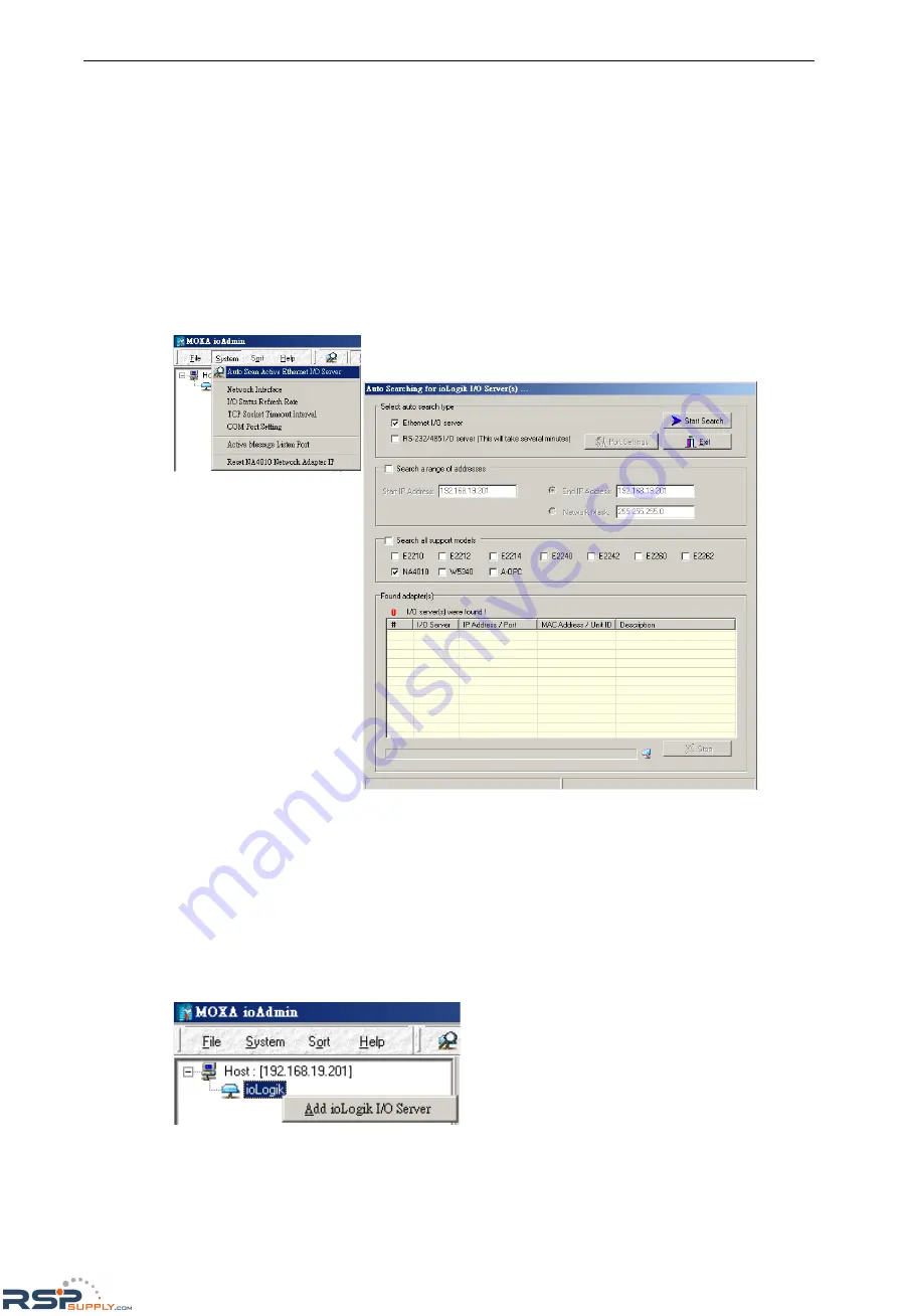
There are two ways to use ioAdmin to link to the Ethernet I/O server: (1) Auto Search, and (2) Manually enter 
the IP address. 

Auto Search 

1.


To start the Auto Search function, click on 

Auto Scan Module(s) 

under 

System


2.


Select 

Ethernet adaptor

, and then click on 

Start Search

. ioAdmin will start searching for installed 

NA-4010’s on the network. 

3.


The Auto Search function can only find Ethernet I/O Servers that are on the same subnet. To connect to 
Ethernet I/O Servers outside the subnet, you will need to add the Ethernet I/O server manually. 

Manually enter the IP address 

1.


To input the Network Adaptor’s IP address manually, click the 

right mouse key

, and then click on 

ioLogik 

in the left ioAdmin frame. 


RSPSupply  -  1-888-532-2706 -  www.RSPSupply.com

http://www.RSPSupply.com/p-11304-Moxa-NA-4010.aspx

Summary of Contents for ioLogik 4000 Series

Page 1: ...gik 4000 Series User s Manual Fourth Edition December 2012 www moxa com product 2012 Moxa Inc All rights reserved RSPSupply 1 888 532 2706 www RSPSupply com http www RSPSupply com p 11304 Moxa NA 4010 aspx ...

Page 2: ... programs described in this manual at any time Information provided in this manual is intended to be accurate and reliable However Moxa assumes no responsibility for its use or for any infringements on the rights of third parties that may result from its use This product might include unintentional technical or typographical errors Changes are periodically made to the information herein to correct...

Page 3: ...igital outputs sink type 24 VDC 0 3 A 1 10 M 2601 16 digital outputs source type 24 VDC 0 3 A 1 10 M 2450 4 relay outputs 24 VDC 230 VAC 2 A 1 10 Power Modules 1 11 M 7001 System power module 1 11 M 7002 Field power module 1 11 M 7804 0 VDC 1 11 M 7805 24 VDC 1 11 Temperature Input Modules 1 12 M 6200 2 analog inputs RTD PT100 JPT100 1 12 M 6201 2 analog inputs thermocouple 1 12 2 Hardware Install...

Page 4: ...erver to ioAdmin 3 13 Starting ioAdmin 3 13 Linking to the RS 232 485 Server 3 14 Password Protection 3 16 Reset to Default 3 16 Restarting the System 3 17 Deleting an I O Server from the List 3 17 Watchdog Timer 3 17 Firmware Update 3 17 I O Status Refresh Rate 3 17 Modbus Address Mapping 3 18 Finding a Modbus Address for I O Channels 3 18 Exporting Modbus Address Settings 3 18 4 Configuring I O ...

Page 5: ...m Overview Package List Product Features Product Descriptions Network Adaptors Analog Input Modules Analog Output Modules Digital Input Modules Digital Output Modules Power Modules Temperature Input Modules Specifications Adaptors Analog Input Modules Analog Output Modules Digital Input Modules Digital Output Modules Power Modules Temperature Input Modules RSPSupply 1 888 532 2706 www RSPSupply co...

Page 6: ...odules with up to 512 DIOs or 128 AIOs Network Adaptor Digital Input Digital Output Analog Input Analog Output Special Modules Type Type Ch Type Ch Type Ch Type Ch Type Ch Ethernet 24 VDC 8 16 24 VDC 8 16 4 20 mA 8 4 20 mA 4 Encoder 24 V 1 RS 485 48 VDC 4 125 VAC 4 0 10 V 8 0 10 V 4 RS 232 110 VAC 4 230 VAC 4 RTD 2 230 VAC 4 TC 2 Package List Each Network Adaptor and I O module is packed securely ...

Page 7: ... remote and local management Easy to use DLL library for easy user programming Product Descriptions Network Adaptors Model Name Description NA 4010 Ethernet network adaptor Modbus TCP NA 4020 RS 485 network adaptor Modbus RTU NA 4021 RS 232 network adaptor Modbus RTU Analog Input Modules Model Name Description M 3802 8 AIs current 4 20 mA 12 bit RTB M 3810 8 AI voltage 0 10 V 12 bit RTB M 6200 2 A...

Page 8: ...module with 8 channels 24 VDC output RTB 10 to 60 C operating temperature Temperature Input Modules Model Name Description M 6200 Modular remote I O module with 2 RTDs RTB 10 to 60 C operating temperature M 6201 Modular remote I O module with 2 TCs RTB 10 to 60 C operating temperature Specifications Adaptors NA 4010 LAN Ethernet 1 x 10 100 Mbps RJ45 Software Features Protocols Modbus TCP HTTP Boot...

Page 9: ...and NA 4020 4021 Field Power Rated Voltage 11 to 28 8 VDC 24 VDC typical Current in Field Power Contact Max 10 A Isolation System Power to I O Driver Optical isolation Physical Characteristics Dimensions 45 x 99 x 70 mm 1 77 x 3 90 x 2 76 in Weight 150 g Mounting DIN rail Environmental Limits Operating Temperature 10 to 60 C 14 to 140 F Storage Temperature 40 to 85 C 40 to 185 F Ambient Relative H...

Page 10: ...mat 16 bit integer 2 s complement Accuracy 0 1 FSR 25 C 0 3 FSR 0 C 60 C Input Impedance 500K ohms Conversion Time 4 ms for all channels Power Consumption 60 mA 5 VDC Isolation I O to logic photocoupler isolation Wiring I O cable max AWG14 MTBF 7 288 320 hrs Database Telcordia Bellcore Analog Output Modules M 4402 4 analog outputs 4 to 20 mA 12 bits Analog Outputs 4 channels Resolution in Ranges 1...

Page 11: ...5 VDC On state Current 6 mA point 28 8 VDC max Input Impedance 5 1K ohms typical Filtering Time 1 5 ms typical Common Type External common single common Power Consumption 35 mA 5 VDC Isolation I O to logic photocoupler isolation Wiring I O cable max AWG14 MTBF 15 759 240 hrs Database Telcordia Bellcore M 1801 8 digital inputs source type 24 VDC Digital Inputs 8 channels Type source On state Voltag...

Page 12: ...oltage 0 to 5 VDC On state Current 6 mA point 28 8 VDC max Input Impedance 5 1K ohms typical Filtering Time 1 5 ms typical Common Type 16 channels for 2 COMs single common Power Consumption 40 mA 5 VDC Isolation I O to logic photocoupler isolation Wiring I O flat cable 20 pin MTBF 11 694 600 hrs Database Telcordia Bellcore M 1450 4 digital inputs 110 VAC Digital Inputs 4 channels 110 VAC On state ...

Page 13: ...er channel min Off Leakage Current 50 µA max Current Rating 0 5 A per channel Common Type 8 channels per external common single common Power Consumption 60 mA 5 VDC Isolation I O to logic photocoupler isolation Wiring I O cable max AWG14 MTBF 13 884 600 hrs Database Telcordia Bellcore M 2801 8 digital outputs source type 24 VDC 0 5 A Digital Outputs 8 channels Type source Output Range 24 VDC nomin...

Page 14: ...Type 8 channels per external common single common Power Consumption 60 mA 5 VDC Isolation I O to logic photocoupler isolation Wiring I O flat cable 20 pin MTBF 9 749 880 hrs Database Telcordia Bellcore M 2450 4 relay outputs 24 VDC 230 VAC 2 A Relay Outputs 4 channels Relay Type Form A N O Single Pole Single Throw SPST Output Voltage Range Load dependent 5 to 28 8 VDC 2 A resistive 48 VDC 0 8 A re...

Page 15: ...0 hrs Database Telcordia Bellcore M 7002 Field power module Field Power Input Voltage DC 5 VDC 24 VDC 48 VDC AC 110 VAC 220 VAC Current for Field Power Contacts 10 A Max MTBF 75 528 720 hrs Database Telcordia Bellcore M 7804 0 VDC Channels 8 Mode 0 VDC MTBF 73 750 440 hrs Database Telcordia Bellcore M 7805 24 VDC Channels 8 Mode 24 VDC MTBF 73 750 440 hrs Database Telcordia Bellcore RSPSupply 1 88...

Page 16: ...r Consumption 80 mA 5 VDC Isolation I O to logic photocoupler isolation Wiring I O cable max AWG14 MTBF 3 644 160 hrs Database Telcordia Bellcore M 6201 2 analog inputs thermocouple Thermocouple Inputs 2 channels Sensor Types Type J K T E R S B N L U C D mV input 10 µV bit 2 µV bit Resolution 0 1 C 10 µV Data Format 16 bit integer 2 s complement Accuracy 0 1 FSR 25 C 0 3 FSR 0 C 60 C Input Impedan...

Page 17: ...om a DIN Rail Installing an RTB Removable Terminal Block Connecting the Power System Connecting to the Network NA 4010 Ethernet Network Adaptor NA 4020 RS 485 Network Adaptor NA 4021 RS 232 Network Adaptor LED Indicators LED Indicators for Network Adaptors LED Indicators for I O Modules When to Use the Power Expansion Module When to Use the Field Power Distributor When to Use the Potential Distrib...

Page 18: ...n bus Modbus Addresses for each I O channel are arranged dynamically by the network adaptor based on the installed I O modules The network adaptor requires two sets of 24 VDC power inputs One is for the internal logic circuit and the other is for the field I O circuits The network adaptor provides 5 VDC power to all connected I O modules When the total current consumption of the I O modules exceed...

Page 19: ...Appearance Installing I O Modules on a DIN Rail Step 1 Align the I O module and network adaptor side by side making sure the upper and lower rails are hooked Step 2 Push the I O module along the inner rail until it touches the DIN rail and then push hard to clip it onto the DIN rail RSPSupply 1 888 532 2706 www RSPSupply com http www RSPSupply com p 11304 Moxa NA 4010 aspx ...

Page 20: ...er to push down the tab located on the lower part of the module Step 2 Pull out the I O module Installing an RTB Removable Terminal Block Removing the RTB from the I O Module Pull hard to remove the plastic belt from the RTB RSPSupply 1 888 532 2706 www RSPSupply com http www RSPSupply com p 11304 Moxa NA 4010 aspx ...

Page 21: ... field power are provided by different power supply systems Connecting to the Network NA 4010 Ethernet Network Adaptor The NA 4010 Ethernet network adaptor supports standard 10 100 Mbps Ethernet For first time users we recommend that you link from your host computer to the NA 4010 over a local Ethernet network to handle IP and system configuration Once the installation is done you may move the Eth...

Page 22: ...onnecting the NA 4020 to a host computer running the ioAdmin utility Once the I O system is configured you can move the entire system to the field Connecting a Single Serial I O Server RS 485 or RS 232 E g COM1 9600 N 8 1 ioLogik 000 Slic I O Server E g ID 10 NA 4020 RS 485 Port Pin Assignment RSPSupply 1 888 532 2706 www RSPSupply com http www RSPSupply com p 11304 Moxa NA 4010 aspx ...

Page 23: ...e contact your vendor for assistance LINK Green Ethernet connected ACTIVE Green Flashing Transmitting or Receiving data over Ethernet I O Off No I O module detected Green Steady On System bus to I O modules is running normally Flashing System bus to I O modules ready but the network adaptor is not exchanging data with I O modules Red Steady On System bus communication failure Flashing One or more ...

Page 24: ...s Red Steady On System bus communication failure Flashing One or more I O modules are in an error state Note The following situations may cause a red I O LED a I O module plugged in during operation b I O module not firmly locked on the rail c One of the modules is damaged Field Power Off No 24 VDC field power Green 24 VDC field power detected LED Indicators for I O Modules Each DIO or AIO module ...

Page 25: ...odule s terminal block 2 Plug in the network adaptor s terminal block When to Use the Field Power Distributor Most of the field power DIO AIO modules for the ioLogik 4000 series are 24 VDC If you need to connect 48 VDC or 110 VAC 230 VAC digital input or output modules you must use the Field Power Distributor to isolate different field powers within a single ioLogik 4000 system If all of the DIO m...

Page 26: ...oper cabling could cause a fire or electric shock Operating Precautions Do not touch the terminal when the power is on to avoid electric shock Do not assemble the product when the power is on Do not modify the wiring while operating the product Pay attention to the power linkage procedure An incorrect process flow could lead to mechanical damage or other hazards ATTENTION The End Module should be ...

Page 27: ...terval Watchdog Timer Firmware Upgrade Exporting the System Configuration Remote Monitoring I O Status Refresh Rate Checking the Ethernet I O Status via Web Browser NA 4010 only Configuring the NA 4020 4021 s RS 485 232 I O System Configuring Communication Parameters Linking the RS 485 232 I O Server to ioAdmin Password Protection Reset to Default Restarting the System Deleting an I O Server from ...

Page 28: ...rmine whether your ioLogik 4000 needs to use a static IP or dynamic IP BOOTP application 3 If the ioLogik 4000 is used in a static IP environment you can use ioAdmin to configure the new IP address The factory default IP address is 192 168 127 254 4 If the ioLogik 4000 is used in a dynamic IP environment you can use ioAdmin to make sure BOOTP is enabled The factory default for BOOTP is enabled ATT...

Page 29: ...pe the following commands at the Windows DOS prompt Note The MAC address is printed on the left side of the Ethernet network adaptor ping 192 168 123 236 current IP address arp a view Ethernet physical address arp d 192 168 123 236 delete arp table arp s 192 168 123 237 10 00 00 10 00 00 assign static arp table with new IP address ping n 1 l 741 192 168 123 237 assign new IP address arp d clear al...

Page 30: ...e Auto Search function click on Auto Scan Module s under System 2 Select Ethernet adaptor and then click on Start Search ioAdmin will start searching for installed NA 4010 s on the network 3 The Auto Search function can only find Ethernet I O Servers that are on the same subnet To connect to Ethernet I O Servers outside the subnet you will need to add the Ethernet I O server manually Manually ente...

Page 31: ...e indicates the combination of all I O modules by slot number The lower right frame lists detailed information for installed I O modules If you move the mouse cursor over any of the I O modules the model name and description will be displayed automatically At this point your Ethernet I O system should be up and running The next section explains additional ioLogik 4000 management issues You may als...

Page 32: ...iguration tabs Reset to Default The Network Adaptor settings including IP address netmask gateway watchdog timer I O module safety status and temperature sensor parameters are stored in the network adaptor How to Reset to Default Right click on the target I O server and then click on Reset to Default You may need to wait 10 seconds or longer for the process to finish ioAdmin will reconnect the I O...

Page 33: ...ral I O servers appear in ioAdmin s left frame you can delete I O servers from the list to make your management task easier Right click on the target I O server and then press Disconnect Right click on the target I O server and then press Delete I O Server The target I O Server will be removed from the list NOTE The ioLogik must first be disconnected to use this function Network Click on the netwo...

Page 34: ...d unless the host computer actively disconnects the Modbus TCP TCP Socket Timeout Interval The Socket timeout interval in the System menu is used to configure the timeout for each Modbus TCP query from the host computer to the Ethernet network adaptor The unit is seconds RSPSupply 1 888 532 2706 www RSPSupply com http www RSPSupply com p 11304 Moxa NA 4010 aspx ...

Page 35: ...twork adaptor sets all digital output and analog output values to a predefined Safe Status The maximum Timeout Value is 65535 which equals 6553 5 seconds Firmware Upgrade The NA 4010 s firmware can be updated via Ethernet To upgrade the firmware click the Firmware Upgrade tab Click on the file icon and select the firmware Press Upgrade when you re ready During the firmware upgrade DO NOT turn the ...

Page 36: ...d I O servers The default value is 50 500 msec To change the configuration click I O Status Refresh Rate under the System menu and then adjust the data refresh rate Note that the unit is in 10 msec increments so if you enter 50 the refresh rate will be 0 5 sec Checking the Ethernet I O Status via Web Browser NA 4010 only The NA 4010 Ethernet network adaptor can be used to view the adaptor s basic ...

Page 37: ... Click on a slot number to view the status of the module installed in that slot The following example shows the status of a thermocouple module RSPSupply 1 888 532 2706 www RSPSupply com http www RSPSupply com p 11304 Moxa NA 4010 aspx ...

Page 38: ...k side of the connection requires a DB9 connector If your computer does not have an RS 232 port you can install a Moxa multiport serial board for example the CP 132U or use a Moxa USB to serial hub for example the NPort 1220 Connecting a Single Serial I O Server A DIP switch on the NA 4020 4021 s front panel allows you to configure the parameters manually RSPSupply 1 888 532 2706 www RSPSupply com...

Page 39: ... 8 1 Watchdog disabled Modbus RTU NOTE ioAdmin only operates under Modbus RTU The next step is to configure the Unit ID for the I O Server On a Modbus RTU ASCII serial network each node must have a unit ID that ranges from 01 to 99 Use a screw driver to rotate the switch and set the Unit ID The upper switch represents the high digit whereas the lower switch represents the low digit Note that the a...

Page 40: ...1 to 99 for each COM port However it could take a long time to finish the process A more efficient and faster method is to select Only Search COMx and search designated COM ports Note that ioAdmin supports Modbus RTU In a Modbus ASCII environment configure the network adaptor using Modbus RTU and then switch back to Modbus ASCII for field operation Click Port Settings to configure the COM port and...

Page 41: ...d then click on the ioLogik in the left ioAdmin frame Click on NA 4021 choose the connected COM port number and then select the Unit ID for Modbus address Once the RS 232 485 I O server is connected to ioAdmin the following screen will appear RSPSupply 1 888 532 2706 www RSPSupply com http www RSPSupply com p 11304 Moxa NA 4010 aspx ...

Page 42: ...show the Watchdog tab Reset to Default The network adaptor settings watchdog timer setting I O module safety status and temperature sensor parameters are stored in the network adaptor Right click on the target I O server and then click on Reset to Default to proceed You may need to wait 10 seconds or longer ioAdmin will reconnect the I O server automatically Note that this function requires passwo...

Page 43: ...mer monitors the Modbus RTU or Modbus ASCII connection between the Network Adaptor and the host computer The default is off When there is no query from the host computer over a preset time in 100 msec increments the Network Adaptor will set all digital output and analog output values to a predefined Safe Status Whether or not the Network Adaptor is operational and ready for normal operation depend...

Page 44: ...nels are required when you want to access the I O status with SCADA software However it s not easy to memorize all of the addresses for each I O channel For this reason ioAdmin allows you to export a text file containing the installed I O modules and their Modbus addresses The following example is an exported system configuration file 3 Modbus address table Slot No Channel No I O type Modbus Addr ...

Page 45: ...ics are covered in this chapter On Line Wiring Guide Digital Input Modules Digital Output Modules Digital Output Module Safe Status Analog Input Modules Analog Output Modules Analog Output Module Safe Status Temperature Sensing Modules RTD Thermocouple RSPSupply 1 888 532 2706 www RSPSupply com http www RSPSupply com p 11304 Moxa NA 4010 aspx ...

Page 46: ...000 is easy to use and ioAdmin comes with an on line I O wiring guide that makes your job easy Use the mouse to move the cursor over any of the I O modules and then click the right mouse button to display a Wiring Guide Click on the wiring guide to show a help file for that model RSPSupply 1 888 532 2706 www RSPSupply com http www RSPSupply com p 11304 Moxa NA 4010 aspx ...

Page 47: ...on the main page to display the I O status on the I O Status tab To check the Modbus Address click on the Modbus Address tab Related Models Digital Input M 1800 8 DI sink 24 VDC RTB M 1801 8 DI source 24 VDC RTB M 1600 16 DI sink 24 VDC RTB M 1601 16 DI source 24 VDC 20 pin M 1450 4 DI 110 VAC RTB M 1451 4 DI 220 VAC RTB RSPSupply 1 888 532 2706 www RSPSupply com http www RSPSupply com p 11304 Mox...

Page 48: ...tput channel We use M 2404 to illustrate To check the DI channel status click on the I O module on the main page You will see the I O status on the I O Status tab To check the Modbus Address click on the Modbus Address tab RSPSupply 1 888 532 2706 www RSPSupply com http www RSPSupply com p 11304 Moxa NA 4010 aspx ...

Page 49: ...ule You can test to make sure the digital output channel works over the network Click on the Test tab on the Config page Press the switch and then press Test At this point you can change the status of the digital output point Related Models Digital Input M 2800 8 DOs sink MOSFET 24 VDC 0 5 A RTB M 2801 8 DOs source MOSFET 24 VDC 0 5 A RTB M 2600 16 DOs sink MOSFET 24 VDC 0 3 A 20 pins M 2601 16 DO...

Page 50: ...ress tab Related Models Digital Input M 3802 8 AIs current 4 20 mA 12 bit RTB M 3810 8 AIs voltage 0 10 V 12 bit RTB Analog Output Modules This section describes how to configure an analog output module We use the M 4211 to illustrate To check the status of an analog output channel click on the I O module on the main page The I O status will be displayed on the I O Status tab To check the Modbus A...

Page 51: ... 0 to 10 V analog output module the Low Limit is 0 V High Limit represents the highest value for the analog output module For a 0 to 10 V analog output module the High Limit is 10 V You can test if the analog output channel really works over the network Click on the Test tab on the Config page Scroll the output level and then press Test At this point you can change the level of the analog output p...

Page 52: ...Modbus Address click on the Modbus Address tab The RTD module supports different kinds of temperature sensors To configure the sensor type click on config On this page you can set up the sensor types and temperature unit Note that the configuration applies to all channels on the same module The related model is M 6200 The FilterType represents different sampling times In Normal mode the conversion...

Page 53: ...you can set up the sensor types and the temperature unit Note that the configuration applies to all channels on the same module The related model is M 6201 The FilterType represents the different sampling times In Normal mode the conversion time is about 200 ms In Enhanced mode the conversion time will be about double or around 400 ms The thermocouple temperature sensor is noise sensitive Using En...

Page 54: ... in this chapter Overview What is MXIO DLL Library How to install MXIO DLL Library MXIO Function Groups System Commands Modbus Command Sets Direct I O Command Sets RSPSupply 1 888 532 2706 www RSPSupply com http www RSPSupply com p 11304 Moxa NA 4010 aspx ...

Page 55: ...ith the ioAdmin software utility It is installed in the directory Start Programs Moxa IO Server Library Refer to MXIO DLL help for details MXIO Function Groups System Commands RS 485 RS 232 I O Connect Commands MXSIO_OpenCommPort MXSIO_CloseCommport MXSIO_Connect MXSIO_Disconnect Ethernet I O Connect Commands MXEIO_Init MXEIO_Exit MXEIO_Connect MXEIO_Disconnect MXEIO_CheckConnection General Comman...

Page 56: ...AI_Reads AI_Read Analog Output Commands AO_Reads AO_Read AO_Writes AO_Write RTD Commands RTD_Reads RTD_Read Thermocouple Commands TC_Reads TC_Read Special Commands for ioLogik 4000 Adp4K_ReadFirmwreRevisi on Adp4K_ReadFirmwareDate Adp4K_ReadSlotAmount Adp4K_ReadStatus Adp4K_ReadAlarmedSlot RSPSupply 1 888 532 2706 www RSPSupply com http www RSPSupply com p 11304 Moxa NA 4010 aspx ...

Page 57: ...e following topics are covered in this appendix Port Pinout Diagrams Ethernet Port Pinouts Serial Port Pinouts Ethernet Cable Wiring Diagrams RSPSupply 1 888 532 2706 www RSPSupply com http www RSPSupply com p 11304 Moxa NA 4010 aspx ...

Page 58: ...ams Ethernet Port Pinouts Pin Signal 1 Tx 2 Tx 3 Rx 6 Rx Serial Port Pinouts NA 4020 RS 485 Network Adaptor Pin Assignment NA 4021 RS 232 Network Adaptor Pin Assignment RSPSupply 1 888 532 2706 www RSPSupply com http www RSPSupply com p 11304 Moxa NA 4010 aspx ...

Page 59: ...ioLogik 4000 Pinouts and Cable Wiring A 3 Ethernet Cable Wiring Diagrams RSPSupply 1 888 532 2706 www RSPSupply com http www RSPSupply com p 11304 Moxa NA 4010 aspx ...

Reviews: