background image

IA3341 Hardware User's Manual 

Hardware Connection Description 


3-2 

Wiring Requirements 

In this section, we describe how to connect various devices to the embedded computer. You should heed the 
following common safety precautions before proceeding with the installation of any electronic device: 


Use separate paths to route wiring for power and devices. If power wiring and device wiring paths must 
cross, make sure the wires are perpendicular at the intersection point. 

NOTE 

Do not run signal or communication wiring and power wiring in the same wire conduit. To avoid interference, 
wires with different signal characteristics should be routed separately. 


You can use the type of signal transmitted through a wire to determine which wires should be kept separate. 
The rule of thumb is that wiring that shares similar electrical characteristics can be bundled together. 


Keep input wiring and output wiring separate. 


When necessary, it is strongly advised that you label wiring to all devices in the system. 


ATTENTION 

Safety First! 

Be sure to disconnect the power cord before doing installations and/or wiring. 

Electrical Current Caution!


Calculate the maximum possible current in each power wire and common wire. Observe all electrical codes 
dictating the maximum current allowable for each wire size. 
If the current goes above the maximum ratings, the wiring could overheat, causing serious damage to your 
equipment. 

Temperature Caution! 

Be careful when handling the unit. When the unit is plugged in, the internal components generate heat, and 
consequently the outer casing may feel hot to the touch. 


Connecting the Power 

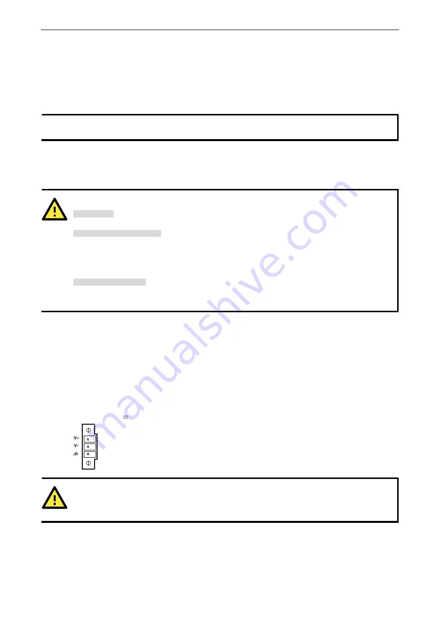
The IA3341 has a 3-pin terminal block for a 12 to 48 VDC power input. 

The following figures show how the power input interface connects to external power sources. If the power is 
properly supplied, the Power LED will light up. The Ready LED will glow a solid green color when the operating 
system is ready (it may take 30 to 60 seconds for the operating system to boot up). 

Terminal Block 

12-48 VDC

Power Input


ATTENTION 

The power for this product is intended to be supplied by a Listed Power Supply Unit that is rated to deliver 12 
to 48 VDC at a minimum of 1200 mA for 12 VDC, and 260 mA for 48 VDC. 


Grounding the Unit 

Grounding and wire routing helps limit the effects of noise due to electromagnetic interference (EMI). Run the 
ground connection from the ground screw to the grounding surface prior to connecting devices. 

Summary of Contents for IA3341

Page 1: ...IA3341 Hardware User s Manual First Edition May 2010 www moxa com product 2010 Moxa Inc All rights reserved Reproduction without permission is prohibited...

Page 2: ...serves the right to make improvements and or changes to this manual or to the products and or the programs described in this manual at any time Information provided in this manual is intended to be ac...

Page 3: ...2 4 Placement Options 2 4 DIN Rail Mounting 2 4 Wall or Cabinet Mounting 2 5 3 Hardware Connection Description 3 1 Wiring Requirements 3 2 Connecting the Power 3 2 Grounding the Unit 3 2 Connecting to...

Page 4: ...computer has 2 analog input channels and 2 thermocouple channels making it the ideal solution for a variety of industrial applications such as solar power and environmental monitoring This manual intr...

Page 5: ...help users easily monitor and retrieve the AI data which is particularly useful for applications such as solar power and environmental monitoring Model Descriptions and Package Checklist IA3341 LX RIS...

Page 6: ...for RS 485 Baudrate 50 bps to 921 6 Kbps supports non standard baudrates see user s manual for details Serial Signals RS 232 TxD RxD DTR DSR RTS CTS DCD GND RS 422 TxD TxD RxD RxD GND RS 485 4w TxD Tx...

Page 7: ...x 3 71 in Mounting DIN Rail wall Environmental Limits Operating Temperature 10 to 60 C 14 to 140 F Operating Humidity 5 to 95 RH Storage Temperature 20 to 80 C 4 to 176 F Anti vibration 2 g rms IEC 60...

Page 8: ...IA3341 Hardware User s Manual Introduction 1 5 Hardware Block Diagram...

Page 9: ...to connect a variety of devices The IA3341 comes with a reliable and stable hardware platform that lets you devote the bulk of your time to application development In this chapter we provide basic in...

Page 10: ...nt View 10 100 Mbps LAN Port x2 RJ45 USB 2 0 Host x1 type A Serial LED x 4 Tx Rx DI x 4 DO x 4 System LED x 3 Power Ready Storage Top Bottom Views Serial Port x2 RS 232 422 485 DB9 Console Port AI x 2...

Page 11: ...smitting TX data to the serial device P1 P2 TX Off Serial port is not transmitting TX data to the serial device Orange Serial port is receiving RX data from the serial device P1 P2 RX Off Serial port...

Page 12: ...ualified Moxa support engineer If you need to change the battery contact the Moxa RMA service team WARNING There is a risk of explosion if the battery is replaced by an incorrect type Placement Option...

Page 13: ...ttachment plate from IA3341 s rear panel and then attach the wall mount plates as shown in the figures below STEP 2 Mounting the IA3341 on the wall requires 4 screws as illustrated in the following fi...

Page 14: ...urposes The following topics are covered in this chapter Wiring Requirements Connecting the Power Grounding the Unit Connecting to the Console Port Connecting to the Network Connecting to a Serial Dev...

Page 15: ...urrent Caution Calculate the maximum possible current in each power wire and common wire Observe all electrical codes dictating the maximum current allowable for each wire size If the current goes abo...

Page 16: ......

Page 17: ...2 RS 422 RS 485 4 wire RS 485 2 wire 1 DCD TxDA TxDA 2 RxD TxDB TxDB 3 TxD RxDB RxDB DataB 4 DTR RxDA RxDA DataA 5 GND GND GND GND 6 DSR 7 RTS 8 CTS Connecting to the DI DO The IA3341 has an 4 ch digi...

Page 18: ...unit in a terminal block The pinouts for the AI and thermocouples are shown in the figure below Inserting the SD Card The IA3341 has a built in SD card socket that allows users to add additional memo...

Page 19: ...ged in 4 When finished use screws to attach the protective cover to the computer ATTENTION The IA3341 does not support SD hot swap and PnP Plug and Play function It is necessary to remove power source...

Page 20: ...to provide reasonable protection against harmful interference when the equipment is operated in a commercial environment This equipment generates uses and can radiate radio frequency energy and if no...

Reviews: