- 8 -
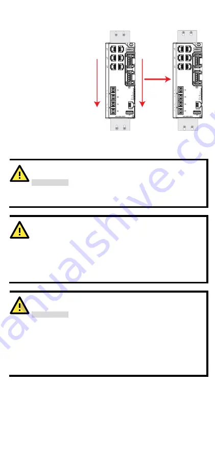
STEP 3—
Once the screws are
fixed to the wall, insert the
four screw heads through the
wide parts of the keyhole-
shaped apertures, and then
slide the EDS device
downwards, as indicated in
the figure at the right.
Tighten the four screws for
more stability.
Wiring Requirements
ATTENTION
Safety First!
External metal parts are hot. Take the necessary precautions if
you are required to handle the device.
ATTENTION
In order to ensure reliable operations, please make sure the
operating temperature of the environment does not exceed the
specifications. When mounting an EDS device with other
operating units in a cabinet without forced ventilation, a
minimum of 4 cm space on both the left and right of the switch
is recommended.
ATTENTION
Safety First!
Be sure to disconnect the power cord before installing and/or
wiring your EDS device. Calculate the maximum possible
current in each power wire and common wire. Observe all
electrical codes dictating the maximum current allowable for
each wire size. If the current goes above the maximum ratings,
the wiring could overheat, causing serious damage to your
equipment.
Be sure to read and follow these important points below:
•
Use separate paths to route wiring for power and devices. If power
wiring and device wiring paths must cross, make sure the wires are
perpendicular at the intersection point.
Summary of Contents for EDS-4008-2GT-2GS
Page 5: ...5 EDS 4008 2MST T Models...


