AIG-300 Series HW UM
Hardware Connection Description
3-3
Grounding the Unit
There is a grounding connector on the top panel of the device. Use this connector to connect a well-
grounded mounting surface, such as a metal panel. Grounding and wire routing help limit the effects of
noise due to electromagnetic interference (EMI).
ATTENTION
A shielded power cord is required to meet the FCC emission limits and to prevent interference with nearby
radio and television reception. It is essential that only the supplied power cord be used.
You are cautioned that changes or modifications not expressly approved by the party responsible for
compliance could void your authority to operate the equipment.
Connecting to the Network
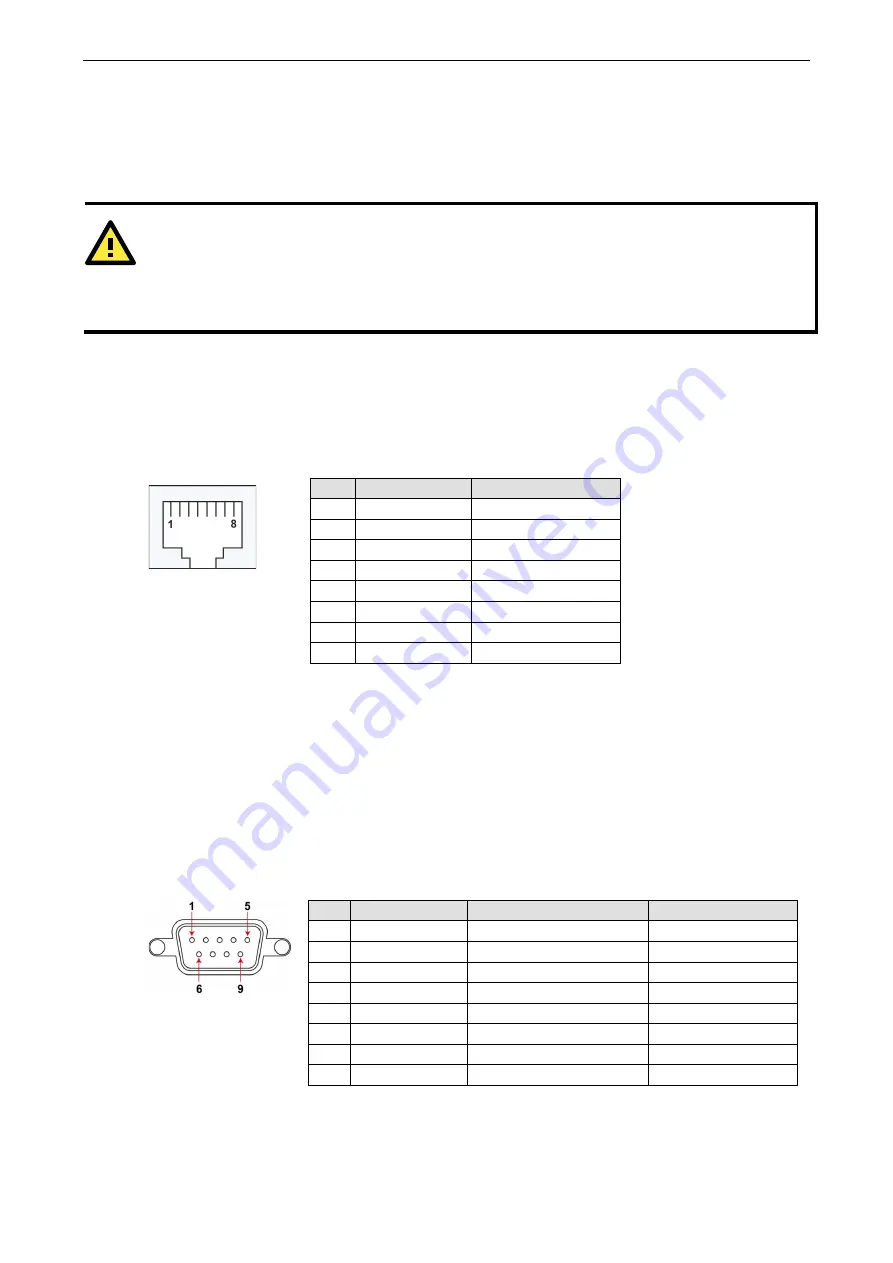
The Ethernet ports are located on the front panel of the device. The pin assignments for the Ethernet ports
are shown in the following figure. If you are using your own cable, make sure that the pin assignments on
the Ethernet cable connector match the pin assignments on the Ethernet port.
Pin
10/100 Mbps
1000 Mbps
1
Tx+
TRD(0)+
2
Tx-
TRD(0)-
3
Rx+
TRD(1)+
4
–
TRD(2)+
5
–
TRD(2)-
6
Rx-
TRD(1)-
7
–
TRD(3)+
8
–
TRD(3)-
Connecting to a USB Device
The device comes with a USB port located on the lower part of the front panel, allowing users to connect to
a device with an USB interface. The USB port uses a type-A connector.
Connecting to Serial Ports
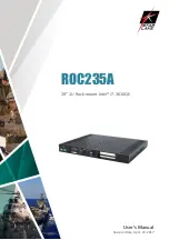
The serial ports can be configured by software for RS-232, RS-422, or RS-485. The pin assignments for the
ports are shown in the following table:
Pin
RS-232
RS-422/RS-485 4w
RS-485 2w
1
–
TxD-(A)
–
2
RxD
TxD+(B)
–
3
TxD
RxD+(B)
Data+(B)
4
DTR
RxD-(A)
Data-(A)
5
GND
GND
GND
6
DSR
–
–
7
RTS
–
–
8
CTS
–
–


