background image

3

1 - GENERAL INSTRUCTIONS

Mottura Serrature di Sicurezza S.p.A. thanks you for choosing this product and reminds you:

-   To read all of these instructions very carefully before installing the lock or doing any maintenance work on the product.
-   That all assembly and connection procedures must be done in conformity to the rules of Good Practice and to current law. DO NOT install this 

product in rooms or atmospheres at risk of explosion or in the presence of flammable fumes/gases.

-  Do not install the lock on doors with risk of contact with water or atmospheric agents if not properly protected.
-   To switch off the power supply and disconnect all live parts before doing any installation or maintenance work on the product. Take all possi-

ble precautions to eliminate the risk of electrical shock when doing the installation or maintenance procedures described in this manual.

-   The installer must deliver these instructions and all of the maintenance instructions to the user.
-   Keep these instructions for future reference and attach the sales receipt to validate the warranty.
-   In case of problems contact authorized dealers only.

Mottura Serrature di Sicurezza S.p.A. may change the characteristics of the products described in these instructions at any time and without notice.

1.1 - WARRANTY TERMS

This product has been inspected by Mottura Serrature di Sicurezza S.p.A. and is guaranteed to be free of all manufacturing defects for the time 
specified by current Italian law, starting on the date of purchase indicated on the sales receipt.
The warranty is in force if the sales receipt, showing details identifying the product, is exhibited to customer service personnel.
The warranty covers the replacement or repair of parts found defective at origin due to manufacturing defects. Costs of shipping to and from 
service centers will be paid by the customer.
In case of repeated malfunctions of the same type or unrepairable defects, Mottura Serrature di Sicurezza S.p.A. may, at its own discretion, replace 
the complete product. The warranty on the replaced product will continue until expiration of the original warranty.
If work is necessary at the customer’s home, the customer will be required to pay a charge for the costs of transfer of authorized technical person-
nel.
Transport will be at the customer’s risk if the product is sent by the customer and at the authorized technician’s risk if the product is picked up and 
transported by the technician.

1.2 - LIMITS OF LIABILITY

The warranty does not cover damage due to:

- negligence, carelessness or use in any manner not described in these instructions
- lack of protection of the lock prior to carrying out any work operations on the door, such as drilling or welding (welds, panel holes, structure 

holes, etc.), which may generate waste materials that will hinder the correct operation of the lock upon entering its mechanism

- maintenance performed in any manner not described in these instructions or by unauthorized personnel
- use of non-original accessories/components Mottura
- transport without the necessary precautions

 and from any circumstances that cannot be attributed to manufacturing defects.
Work temperature: -10°C to +55°C. The batteries guarantee correct operation of the lock in the specified temperature range. If such temperature 
extremes are approached or exceeded, battery performance may decrease rapidly, with possible malfunction of the electrical part. In case of ex-
tremely low temperatures, it is advisable to power the lock from the mains by using the 230/12 V transformer.
In addition, Mottura Serrature di Sicurezza S.p.A. declines all liability for any damage to persons or property deriving from failure to observe all of 
the precautions described herein.

N.B. Mechanical lock operation is guaranteed even when the electronics of the lock has no anomaly. This excludes any electronic 

safety level. Mechanical keys should therefore only be used by the owner and/or by extremely trustworthy persons.

Summary of Contents for Xmode F1.0

Page 1: ...POWERED ELECTRONIC LOCK OPERATION AND MAINTENANCE INSTRUCTIONS USER MANUAL GLUE THE LOCK SYSTEM CODE LABEL HERE SYSTEM CODE RECHARGEABLE M 2 0 F1 0 ...

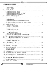
Page 2: ...SABLING SERVICE TAG KEYS 5 4 RESETTING SERVICE TAG KEYS 5 5 DELETING INDIVIDUAL TAG KEYS 5 6 DELETING ALL TAG KEYS 6 LOCK OPERATION MODES 10 6 1 PROGRAMMING LOCK OPERATION MODES 6 2 ACTIVATING DEACTIVATING THE SECURITY CODE FROM THE INSIDE 7 LOCK OPERATION WITH TAG KEYS 11 8 LOCK OPERATION WITH KEYPAD AND TAG KEYS 12 8 1 MEMORIZING PERSONAL ACCESS CODES 8 2 DELETING A PERSONAL ACCESS CODE 8 3 DELE...

Page 3: ...nctions of the same type or unrepairable defects Mottura Serrature di Sicurezza S p A may at its own discretion replace the complete product The warranty on the replaced product will continue until expiration of the original warranty If work is necessary at the customer s home the customer will be required to pay a charge for the costs of transfer of authorized technical person nel Transport will ...

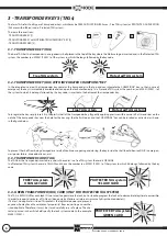
Page 4: ...BLUELEDsteadyon gridpower GREENLEDsteadyon power batteriesefficient BLUE LED steady on GREEN steady on grid battery power YELLOWLEDsteadyon 3beeps remindertoreplacebatteries YELLOWLEDsteadyon doublehigh lowsound batteriesdrained The reminder to replace the batteries is given before any operation is done opening closing etc You should replace the batteries as soon as possible to ensure correct fun ...

Page 5: ...ad lets you enter a PIN 3 to 8 digits with which to operate the lock transponder key TAG the escutcheon checks the presence of a transponder key TAG positioned close to the MM logo at the bottom zone B The function keys are number keys to enter codes P Programming to enter the programming phase E Enter to open close the door after entering the code in normal use confirms a selection in programming...

Page 6: ...e TAG has the transponder inserted in a card in the center In a free TAG system the card is ORANGE In a Protected TAG system the card is YELLOW and shows the number ex M0001 F0001 of the system to which it belongs followed by the key code To prevent the shell from being damaged as a result of continuous opening and closing the key inside the shell should be used ONLY in emergen cies power failure ...

Page 7: ...the system memory see paragraph 5 6 then re memorize all of the TAGs remaining in your possession see paragraphs 5 1 5 2 accor ding to the required hierarchy master service If a TAG with integrated key is lost or stolen you should replace the cylinder and keys as well If aTAG with duplicates TAG with same code is lost or stolen you have to completely delete all of the TAGs in the system memory see...

Page 8: ... UP arrow key and then place theTAG that you want to program at master level close to the exter nal escutcheon scanner A multi tone sound from the buzzer confirms that the TAG has been memorized in this phase the LEDs can be ignored because they indicate the status enabled disabled of the service TAGs In case of error the buzzer gives a rapid double high low sound with flashing of the YELLOW LED i...

Page 9: ...the buzzer sounds about 3 seconds Keep the TAG to be deleted close to the external escutcheon scanner and simultaneously keep E pressed on the internal escutcheon for at least 3 seconds The buzzer will give a long sound to confirm that the TAG has been deleted In case of error it will give an alternating bi tonal sound if the TAG is not in the internal databa se or 5 beeps ONLY in a FREE TAG SYSTE...

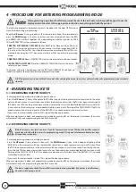
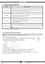
Page 10: ...loses the bolts LATCHBOLTS ONLY When an operation is requested if the lock was closed it opens the bolts if it was open it closes the bolts The spring latch is never operated electronically to open the door you have to operate it manually with the handle This operating mode requires the spring latch handle to be present on both sides of the door Enter programming mode as described in point 4 Press...

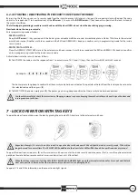
Page 11: ...ide to prevent children or strangers from opening closing the door The code consists of a sequence of 1 to 4 combinations of the UP arrow key and the DOWN arrow key needed to open close the lock instead of the usual enter E key The buzzer gives a long beep to confirm that the security code has been activated To open close the lock from the inside you have to enter the selected code and then press ...

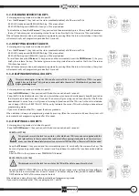
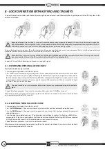
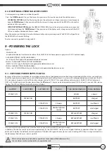
Page 12: ...reset code Enter programming mode as described in point 4 Press the P key to enter code programming mode Enter a code composed of a minimum of 3 to a maximum of 8 digits then confirm by pressing E The flashing GREEN LED accompanied by 3 high low sounds confirm that the code has been memorized The flashing RED LED accompanied by 2 high low sounds means that the entered code is already in memory The...

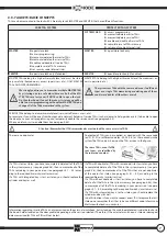
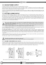
Page 13: ...ans of the internal escutcheon for escutcheon display refer to the appropriate instruction manual provided with the article you can always check the type of power supply and in case of battery power check the charge level In systems with rechargeable batteries disconnect the 230 VAC main power supply to switch off the battery charger and wait AT LEAST 15 seconds before continuing note the BLUE LED...

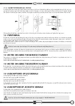
Page 14: ...orrect operation of the lock and correct scanning of transponder keys are not guaranteed When the battery charge is no longer sufficient to operate the lock a double high low sound and lighting of theYELLOW LED require their replacement In any case you should replace the batteries once a year Follow these instructions when replacing the batteries Never use rechargeable batteries if your system req...

Page 15: ...MOTE CONTROL MANUAL N B Do not connect any type of voltage to the cable doing so will permanently damage the lock 13 NOTES ON USING THE SERVICE CYLINDER 14 NOTES ON USING THE MASTER CYLINDER Top position It is designed to overcome power failures or possible malfunctions of the electronic part Therefore it is preferable not to use it in normal operating conditions It must never be used when the loc...

Page 16: ...gistered Enter the programming menu and register the tran sponder After pressing the E key on the internal escutcheon there is an immediate single low sound The lock is communicating with another device con nected to it on the RS485 communication line The lock is in programming phase Wait for the dialog to end and for the lock to return to stand by then try the operation again Exit programming and...

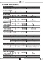
Page 17: ...LLOW steady on 3 beeps CHECK TYPE OF POWER GREEN LED RED LED BLUE YELLOW LED BUZZER INTERNAL ESCUTCHEON Fixed BATTERY BLUE steady on MAINS PROGRAMMING GREEN LED RED LED BLUE YELLOW LED BUZZER INTERNAL ESCUTCHEON Fixed Fixed 3 beeps EXTERNAL ESCUTCHEON Fixed Fixed 3 beeps MASTER TAG ACTIVATION GREEN LED RED LED BLUE YELLOW LED BUZZER INTERNAL ESCUTCHEON multi tone sound Activation YELLOW flashing d...

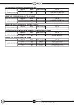
Page 18: ...activation ACTIVATION OF NUMERICAL KEYPAD CODES GREEN LED RED LED BLUE YELLOW LED BUZZER EXTERNAL ESCUTCHEON Flashing 3 low high sounds memorization Flashing 2 low high sounds code already inserted Flashing 2 low high sounds insertion error DELETION OF NUMERICAL KEYPAD CODES GREEN LED RED LED BLUE YELLOW LED BUZZER EXTERNAL ESCUTCHEON Flashing 3 high low sounds deletion Flashing 2 low high sounds ...

Page 19: ...19 NOTE ...

Page 20: ...99286GB 06 14 a_013334 SAFEGUARDINGYOUR SECURITY www mottura it ...

Reviews: