SAFETY PRECAUTIONS AND ELECTRICAL REQUIREMENTS
WARNING: TO REDUCE THE RISK OF FIRE OR ELECTRICAL SHOCK, DO NOT EXPOSE THIS APPLIANCE TO RAIN OR OTHER MOISTURE.
CAUTION: TO REDUCE THE RISK OF ELECTRICAL SHOCK, DO NOT REMOVE COVER. NO USER-SERVICEABLE PARTS INSIDE. REFER SERVICING TO
QUALIFIED SERVICE PERSONNEL.
WARNING: DO NOT PERMIT FINGERS TO TOUCH THE TERMINALS OF PLUGS WHEN INSTALLING OR REMOVING THE PLUG TO OR FROM THE OUTLET.
WARNING: IF NOT PROPERLY GROUNDED YOUR MOTU AUDIO INTERFACE COULD CAUSE AN ELECTRICAL SHOCK.
Your MOTU audio interface is equipped with a three-conductor cord and grounding type plug which has a grounding prong, approved by Underwriters' Laboratories and the Canadian Standards Association.
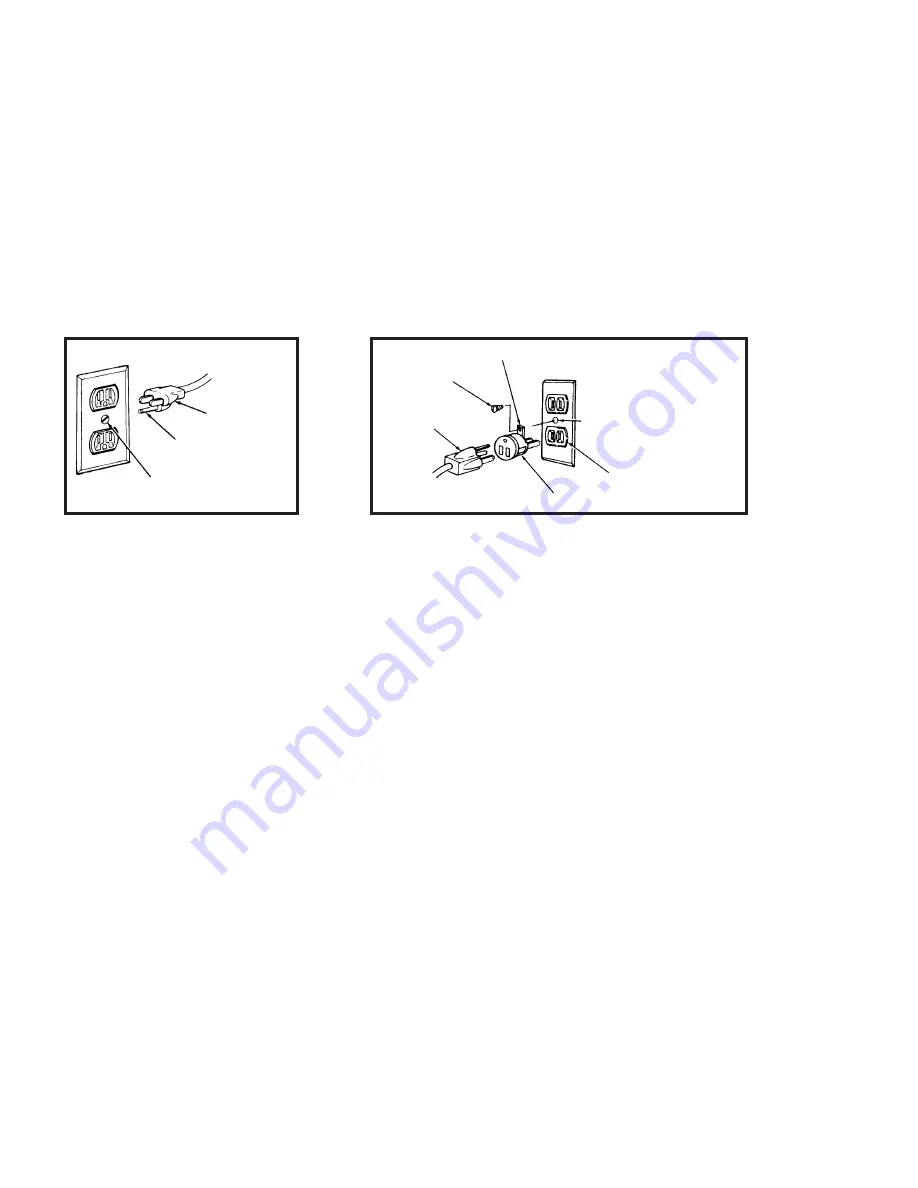
This plug requires a mating three-conductor grounded type outlet as shown in Figure A below.
If the outlet you are planning to use for your MOTU audio interface is of the two prong type, DO NOT REMOVE OR ALTER THE GROUNDING PRONG IN ANY MANNER. Use an adapter as shown below
and always connect the grounding lug to a known ground. It is recommended that you have a qualified electrician replace the TWO prong outlet with a properly grounded THREE prong outlet. An adapter
as illustrated below in Figure B is available for connecting plugs to two-prong receptacles.
WARNING: THE GREEN GROUNDING LUG EXTENDING FROM THE ADAPTER MUST BE CONNECTED TO A PERMANENT GROUND SUCH AS TO A PROPERLY
GROUNDED OUTLET BOX. NOT ALL OUTLET BOXES ARE PROPERLY GROUNDED.
If you are not sure that your outlet box is properly grounded, have it checked by a qualified electrician. NOTE: The adapter illustrated is for use only if you already have a properly grounded two-prong
receptacle. Adapter is not allowed in Canada by the Canadian Electrical Code. Use only three wire extension cords which have three-prong grounding type plugs and three-prong receptacles which will
accept your MOTU audio interface’s plug.
IMPORTANT SAFEGUARDS
1. Read instructions - All the safety and operating instructions should be read before operating your MOTU audio interface.
2. Retain instructions - The safety instructions and owner's manual should be retained for future reference.
3. Heed Warnings - All warnings on your MOTU audio interface and in the owner's manual should be adhered to.
4. Follow Instructions - All operating and use instructions should be followed.
5. Cleaning - Unplug your MOTU audio interface from the computer before cleaning and use a damp cloth. Do not use liquid or aerosol cleaners.
6. Overloading - Do not overload wall outlets and extension cords as this can result in a risk of fire or electrical shock.
7. Power Sources - This MOTU interface should be operated only from the type of power source indicated on the marking label. If you are not sure of the type of power supply to your location, consult your local power company.
8. Power-Cord Protection - Power-supply cords should be routed so that they are not likely to be walked on or pinched by items placed upon or against them. Pay particular attention to cords and plugs, convenience receptacles, and the point
where they exit from your MOTU audio interface.
9. Lightning - For added protection for your MOTU audio interface during a lightning storm, unplug it from the wall outlet. This will prevent damage to your MOTU audio interface due to lightning and power line surges.
10. Servicing - Do not attempt to service this MOTU interface yourself as opening or removing covers will expose you to dangerous voltage and other hazards. Refer all servicing to qualified service personnel.
11. Damage Requiring Service - Unplug your MOTU audio interface from the computer and refer servicing to qualified service personnel under the following conditions.
a. When the power supply cord or plug is damaged.
b. If liquid has been spilled or objects have fallen into your MOTU audio interface.
c. If your MOTU audio interface has been exposed to rain or water.
d. If your MOTU audio interface does not operate normally by following the operating instructions in the owner's manual.
e. If your MOTU audio interface has been dropped or the cabinet has been damaged.
f. When your MOTU audio interface exhibits a distinct change in performance, this indicates a need for service.
12. Replacement Parts - When replacement parts are required, be sure the service technician has used replacement parts specified by the manufacturer or have the same characteristics as the original part. Unauthorized substitutions may
result in fire, electric shock or other hazards.
13. Safety Check - Upon completion of any service or repairs to this MOTU interface, ask the service technician to perform safety checks to determine that the product is in safe operating conditions.
ENVIRONMENT
Operating Temperature: 10°C to 40°C (50°F to 104°)
AVOID THE HAZARDS OF ELECTRICAL SHOCK AND FIRE
Do not handle the power cord with wet hands. Do not pull on the power cord when disconnecting it from an AC wall outlet. Grasp it by the plug.
INPUT
Line Voltage: 100 - 120 volts AC, RMS (US and Japan) or 220 - 250 volts AC, RMS (Europe). Frequency: 47 - 63 Hz single phase. Power: 7 watts maximum.
CAUTION: DANGER OF EXPLOSION IF BATTERY IS REPLACED. REPLACE ONLY WITH THE SAME OR EQUIVALENT TYPE RECOMMENDED BYMANUFAC-
TURER. DISPOSE OF USED BATTERY ACCORDING TO MANUFACTURER’S INSTRUCTIONS.
3-prong plug
Grounding prong
Properly grounded 3-prong outlet
Grounding lug
Screw
3-prong plug
Adapter
Make sure this is connected
to a known ground.
Two-prong receptacle
Figure A
Figure B


