background image

Pb340_01d_oi_e.doc / Apr-16 


Page 4 / 15 

1.3


Installation 

The device is only allowed to be installed and operated within the permissible temperature 
range. Please ensure an adequate ventilation and avoid all direct contact between the device 
and hot or aggressive gases and liquids.  


Before installation or maintenance, the unit must be disconnected from all voltage-sources. 
Further it must be ensured that no danger can arise by touching the disconnected voltage-
sources. 


Devices which are supplied by AC-voltages, must be connected exclusively by switches, 
respectively circuit-breakers with the low voltage network. The switch or circuit-breaker must 
be placed as near as possible to the device and further indicated as separator. 


Incoming as well as outgoing wires and wires for extra low voltages (ELV) must be separated 
from dangerous electrical cables (SELV circuits) by using a double resp. increased isolation. 


All selected wires and isolations must be conform to the provided voltage- and temperature-
ranges. Further all country- and application-specific standards, which are relevant for structure, 
form and quality of the wires, must be ensured. Indications about the permissible wire cross-
sections for wiring are described in the Technical Specifications (see chapter 

7

).  


Before first start-up it must be ensured that all connections and wires are firmly seated and 
secured in the screw terminals. All (inclusively unused) terminals must be fastened by turning 
the relevant screws clockwise up to the stop.  


Overvoltages at the connections must be limited to values in accordance to the overvoltage 
category II.  


For placement, wiring, environmental conditions as well as shielding and earthing/grounding of 
the supply lines the general standards of industrial automation industry and the specific 
shielding instructions of the manufacturer are valid. Please find all respective hints and rules on  

www.motrona.com/download.html

 --> “[General EMC Rules for Wiring, Screening and 

Earthing]”. 
 

1.4


Cleaning, Maintenance and Service Notes 

To clean the front of the unit please use only a slightly damp (not wet!), soft cloth. For the rear 
no cleaning is necessary. For an unscheduled, individual cleaning of the rear the maintenance 
staff or assembler is self-responsible.  


During normal operation no maintenance is necessary. In case of unexpected problems, failures 
or malfunctions the device must be shipped for back to the manufacturer for checking, 
adjustment and reparation (if necessary). Unauthorized opening and repairing can have 
negative effects or failures to the protection-measures of the unit.   

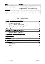
Summary of Contents for PB306

Page 1: ...or displayed PB306 is a simple data preset unit with front sided thumbwheel switches It allows an easy remote setting of single parameters e g speed setting of a drive via fieldbus By pressing the EN...

Page 2: ...e or publication in other electronic and printed media as well as in the internet requires prior written authorization by motrona GmbH Table of Contents 1 Safety Instructions and Responsibility 3 1 1...

Page 3: ...e right to modify the hardware software or operation manual at any time and without prior notice Therefore there might be minor differences between the unit and the descriptions in operation manual Th...

Page 4: ...sections for wiring are described in the Technical Specifications see chapter 7 Before first start up it must be ensured that all connections and wires are firmly seated and secured in the screw term...

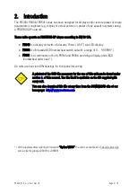
Page 5: ...umbwheel switch set with a range of 0 999 999 PB541 is a combination of both PB340 and PB306 providing a display and a BCD thumbwheel switch set All units are built into DIN housings for front panel m...

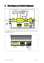
Page 6: ...IL switch BCD Data 3 4 5 2 1 6 Display Processor and Prof ibus controller PB306 PB541 Power Supply 5 0 V 3 3 V PE DC DC PB340 PB541 1M 2n5 DGND Profibus Power supply screw terminals PROFIBUS connector...

Page 7: ...F m Loop resistance 110 km Wire diameter 0 64 mm 0 025 Conductor cross section 0 34 mm Depending on the Baud rate the following maximum cable length must not be exceeded Baud rate kbit s 9 6 19 2 93 7...

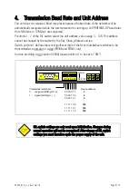
Page 8: ...dress service Switch position 1 defines the most significant digit of the front thumbwheel switches to be transmitted as a numeral or a sign PB306 and PB541 only Version providing a sign option VZ000...

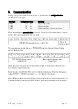
Page 9: ...e user parameter data The diagnosis data provide 6 bytes of PROFIBUS DP diagnosis data and 5 byte of device specific diagnosis data diag 1 diag 2 diag 3 diag 4 Ident high Ident low sign_len 05 hex sta...

Page 10: ...e front LED PB306 Display PB340 PB541 LED PB306 PROFIBUS DP state Device state off Power_on initialization flashing slowly Wait_Prm Wait_Cfg Ready waiting for start up XXXXXX output data on Data_Excha...

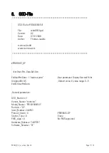
Page 11: ...er Prm Data Def List ExtUserPrmData 1 decimal point User parameter Display Decimal Point Unsigned8 0 0 5 Default value 0 value range 0 5 EndExtUserPrmData General parameters GSD_Revision 1 Vendor_Name...

Page 12: ...00 Redundancy 0 Repeater_Ctrl_Sig 2 RTS Signal CNTR P TTL level 24V_Pins 0 No 24V supply on PROFIBUS connector Implementation_Type DPC31 Slave Specification Freeze_Mode_supp 1 Freeze Mode supported Sy...

Page 13: ...parameter data Module Definition List Module PB340 0xA3 Config PB340 4 byte output data Ext_Module_Prm_Data_Len 1 Ext_User_Prm_Data_Const 0 0x00 Ext_User_Prm_Data_Ref 0 1 EndModule Module PB306 0x93...

Page 14: ...Mounting Dimensions PB306 PB340 PB541 Protection class PB340 PB306 541 Weight PB306 340 PB541 plastic panel outer dimensions w x h x d 96 x 48 x 120 mm 3 78 x 1 89 x 4 72 inch cut out w x h 92 x 43 mm...

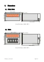
Page 15: ...8 Dimensions 8 1 PB306 PB340 96 0 3 780 48 0 1 890 149 0 5 866 42 5 1 673 9 0 0 354 8 0 0 315 Cut out 92 x 43 mm 3 622 x 1 693 8 2 PB541 96 0 3 780 72 0 2 835 149 0 5 866 66 0 2 598 9 0 0 354 8 0 0 3...

Reviews: