


22.5
60
100
C
Pa
g
.
9
-
M
a
n
u
a
l c
o
d
e:
1
1
9
R
7
1
7
9
G
B
11
9
R
7
1
7
9
G
B
ve
r.
3
.0
3.
0
0
7
/2
0
0
9
- T
h
e d
a
ta a
n
d i
n
fo
rm
ati
o
n i
n
th
is
m
a
n
u
a
l a
re s
u
b
je
ct t
o
c
h
a
n
g
e
at a
n
y ti
m
e
.
6
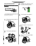
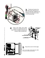
- Position the head bracket onto
the gate leaf at a “C” distance from
the axis of the hinge while taking into
account the A and B measurements as
shown in the table on page 6.
7
- Secure the bracket using securing
elements chosen according to the
gate type and materials.
4
- Secure the base plate, using securing
elements chosen according to the post
type and materials.
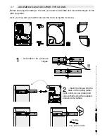
PRELIMINARY OPERATIONS AND BRACKET MOUNTING
5
- Insert the cable feedthroughs and the
cable gland into the base plate holes.