background image

2 - 2

VC6000 Series Product Reference Guide

Installing the VC6000 Series in a Vehicle

Guidelines for Routing Cables

Establish a neat route for the cable, staying clear of moving parts or hot surfaces.

Fix the cable to an existing cable runs inside the vehicle using cable ties.

When the cabling must go through a panel, use a suitable cable guard.

When fixing a conduit or a cable on the outside of a vehicle, use P-Clips. Either drill and tap the hole or use a 
nut and bolt to secure the clip.

Ensure the cable does not have tight bends. The minimum recommended radius is 6.35 cm (2.5 inches).

Ensure cables do not swing or chafe on the structure. This often requires using cable ties approximately 
every one foot, and ensuring the cables do not flex often, especially where they connect to the VC6000 
Series.

If you must re-position the VC6000 Series occasionally, ensure there is enough slack in the cable to 
accommodate movement without putting tension on the cable.

Take the power from as close to the battery terminals as possible, and avoid using existing wiring.

Ensure that all fuses are as close as possible to the power source.

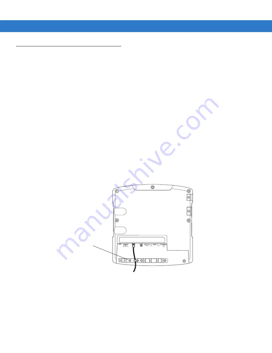
Use plastic cable ties to secure the cables to the cable tie bracket of the VC6000 (see 

Figure 2-1

)..

Figure 2-1    

Cable Tie Bracket

Cable Tie Bracket

Summary of Contents for VC6000 Series

Page 1: ...VC6000 Series Vehicle Computers Product Reference Guide ...

Page 2: ......

Page 3: ...VC6000 Series Product Reference Guide 6802986C08 Rev A December 2008 ...

Page 4: ... part The user agrees not to decompile disassemble decode or reverse engineer any licensed program delivered to the user or any portion thereof Motorola reserves the right to make changes to any software or product to improve reliability function or design Motorola does not assume any product liability arising out of or in connection with the application or use of any product circuit or applicatio...

Page 5: ...iii Revision History Changes to the original manual are listed below Change Date Description 01 Rev A 11 30 2008 Initial release ...

Page 6: ...iv VC6000 Series Product Reference Guide ...

Page 7: ...uments xiv Service Information xiv Chapter 1 Getting Started Introduction 1 1 Unpacking the VC6000 Series 1 1 Optional Accessories 1 2 Model Configurations 1 3 Features 1 3 System Indication LED 1 6 Application LEDs 1 6 Getting Started 1 7 Installing a SIM Card 1 7 Installing an SD Memory Card 1 8 Installing the VC6000 Series 1 8 Starting with the VC6000 Series 1 9 Standby Mode 1 9 Resume from Sta...

Page 8: ...ry Cable 2 6 9 Pin Deutsch Telemetry Cable 2 6 50 Pin Accessory Cable 2 7 Auxiliary Port Pin layout 2 7 Mounting the Combination Antenna VC6096 only 2 10 Installing the GPS Antenna 2 12 Using the VC6000 Series Indoor 2 13 Optional Mounting 2 14 Free standing Pedestal Mount 2 14 Desk Mount 2 15 Mounting Bracket Template for the VC6000 Series 2 15 Chapter 3 Getting Started Series Introduction 3 1 Us...

Page 9: ...he Call History View 4 12 Resetting the Recent Calls Counter 4 12 Deleting Call History Items by Call Date 4 13 Deleting All Call History Items 4 13 Viewing Call Status 4 14 Using the Call History Menu 4 15 Swapping Calls 4 15 Conference Calling 4 16 Text Messaging 4 17 Viewing Text Messages 4 17 Sending a Text Message 4 19 Chapter 5 Wireless Applications Introduction 5 1 Signal Strength Icon 5 2 ...

Page 10: ...Using Serial Port Services 6 18 Personal Area Network Services 6 20 IrMC Synchronization Services 6 20 Bonding with Discovered Device s 6 20 Deleting a Bonded Device 6 22 Accepting a Bond 6 22 Bluetooth Settings 6 23 Device Info Tab 6 23 Services Tab 6 23 Dial Up Networking Service 6 24 File Transfer Service 6 25 Hands Free Audio Gateway Service 6 26 Headset Audio Gateway Service 6 26 IrMC Synchro...

Page 11: ...ne Info 7 48 Network Time Synchronization 7 48 Enhanced Operator Name String 7 49 Service Provider Name Display 7 49 Chapter 8 Using GPS Navigation Introduction 8 1 Software Installation 8 1 VC6000 Series GPS Setup 8 1 Operation 8 2 GPS Maps on microSD Cards 8 2 Answering a Phone Call While Using GPS 8 2 Losing the GPS Signal While in a Vehicle 8 2 Assisted GPS 8 2 Chapter 9 ActiveSync Introductio...

Page 12: ... Product Reference Guide Display 10 2 Connectors 10 2 Cleaning Frequency 10 3 Troubleshooting 10 4 VC6000 Series 10 4 Bluetooth Connection 10 6 Appendix A Specifications VC6096 VC6000 Specifications A 1 Index Glossary ...

Page 13: ... Guide describes how to start using the VC6000 Series Configurations This guide covers the following configurations NOTE Screens and windows pictured in this guide are samples and can differ from actual screens Configuration Operating System GPS Bluetooth Wireless LAN Wireless WAN Vehicle Telemetry VC6000 Windows Mobile 6 1 Classic No Yes No No No VC6096 Windows Mobile 6 1 Professional Yes Yes Yes...

Page 14: ...o operating system or software versions for OEM version Hardware version OEM Software To determine the OEM software version Tap Start Settings System info icon System tab To determine the hardware version Tap Start Settings System Info icon HW Version tab To view the software information Tap Start Settings System Info icon Package tab ...

Page 15: ...s resetting the VC6000 Series entering data Chapter 4 Wireless Applications provides instructions for using and configuring the VC6000 Series on a wireless LAN Chapter 5 Using Bluetooth explains how to use Bluetooth functionality on the VC6000 Series Chapter 6 ActiveSync provides instructions for installing and configuring ActiveSync Chapter 7 Maintenance and Troubleshooting includes instructions ...

Page 16: ... xx Enterprise Mobility Developer Kits EMDKs available at http www motorola com enterprisemobility support For the latest version of this guide and all guides go to www motorola com enterprisemobility manuals Service Information If you have a problem with your equipment contact Motorola Enterprise Mobility Support for your region Contact information is available at www motorola com enterprisemobil...

Page 17: ...olved by Motorola Enterprise Mobility Support you may need to return your equipment for servicing and will be given specific directions Motorola is not responsible for any damages incurred during shipment if the approved shipping container is not used Shipping the units improperly can possibly void the warranty If you purchased your Enterprise Mobility business product from a Motorola business par...

Page 18: ...xvi VC6000 Series Product Reference Guide ...

Page 19: ... Area Network WWAN BluetoothTM and a Global Positioning System GPS receiver Bluetooth technology is used for cordless connection of peripheral devices such as printers bar code scanners handsfree speakers and headsets to the computer Cellular and WiFi radios are used to exchange voice and data with wide and local area networks Among its many communication interfaces the computer contains an intern...

Page 20: ...ovided separately inside the shipping box Table 1 1 Optional Accessories Part Number Description FLN4048 Combination Antenna 8508851K59 External GPS Antenna 0102246H51 Indoor Power Supply Unit 50 16000 221R AC Cord USA 3087568V84 VC6096 WWAN RF Cable 3m 9 8ft 3087568V83 VC6096 WLAN RF Cable 3m 9 8ft 3071815Y17 VC6096 Cigarette Lighter Cable CLA Power Supply Cable 3071815Y13 VC6096 Vehicle Power Ca...

Page 21: ...nication GSM cellular radio and High Speed Downlink Packet Access HSDPA VC6096 only 10 100 Ethernet port for connection to Local Area Network LAN Vehicle motion and location detection via the vehicle telemetry and the GPS receiver VC6096 only Serial RS232 interface Full speed USB ports Wide range of input power 10 V DC to 33 V DC to accommodate a wide range of vehicles Reliable operation in cold e...

Page 22: ... refer to the Enterprise Mobility Developer Kits EMDKs Volume up down Key Application LEDs two Green LEDs Driven by Application1 Power Button with System Indication LED Brightness up down Key Microphone embedded Full QWERTY Keypad Left Soft Key Right Soft Key Call Key Model VC6096 Home Key Model VC6000 End Key Model VC6096 Back Key Model VC6000 Navigation Key Select Key Speaker embedded Function K...

Page 23: ... 6 To activate the 10 100 Ethernet LAN Port refer to Ethernet LAN Power program in Table on page 3 8 Auxiliary Port 2 3 M4 Ground Screw Boss M4 Screw Mounting Bosses Power Connector GPS Antenna Connector used in VC6096 only WWAN Antenna Connector 1 used in VC6096 only WLAN Antenna Connector 1 used in VC6096 only Mini USB Port Type B 2 USB Port Type A 2 10 100 Ethernet LAN Port 2 4 SIM Card Slot us...

Page 24: ...n of Application LEDs refer to the operating manual provided by your organization Table 1 3 LED Indications LED State Indication Off Normal operation Fast flashing amber Critical power event Input power is out of operating range The computer may turn off save your entries Vehicle engine start no action is required Cold reset is active no action is required Slowly flashing amber Critical temperatur...

Page 25: ...the VC6096 including network activation and phone book entries To install the SIM card 1 Remove the T8 screw that secures the SIM card door and open the door 2 Position the SIM card with the contacts facing the back of the VC6096 and insert into the SIM slot The SIM card corner notch fits into the slot only one way see Figure 1 3 3 Use a pen to push the SIM card inwards to lock 4 Place the SIM car...

Page 26: ...mory card with the contacts facing the back of the VC6000 Series and insert into the Memory Card Slot The corner notch of the SD memory card fits into the Memory Card slot only one way 3 Use your a pen to push the SD memory card inwards to lock 4 Replace the Protective Rubber Cap to seal the Memory card slot Figure 1 4 SD Card Installation Installing the VC6000 Series Refer to Chapter 2 Installati...

Page 27: ... resume from Standby mode when turning On the ignition key connecting or removing a USB device pressing a keyboard key receiving an alarm pressing the touch screen communicating over Bluetooth communicating over WWAN Telemetry signal 1939 protocol only Ethernet signal magicPacket GPIO signal To program the operation of Standby mode refer to the VC6000 Series Software Enterprise Mobility Developer ...

Page 28: ...25 seconds Clean Boot Clean boot may become necessary when your VC6000 Series is jammed and does not respond to cold boot A clean boot resets the VC6000 Series to the factory default settings All applications installed by your organization are erased and should be re installed on the VC6000 Series To perform a clean boot Press and hold Suspend Button Left Soft Key The VC6000 Series starts to boot ...

Page 29: ...ide injury the VC6000 Series must be firmly secured to a surface of the vehicle that can support the VC6000 Series weight in extream driving conditions Do not install the VC6000 Series or any accessory in a location that affects the vehicle safety driveability or visibility CAUTION The installation of the VC6000 Series should be performed in accordance with your organization procedures and require...

Page 30: ...he minimum recommended radius is 6 35 cm 2 5 inches Ensure cables do not swing or chafe on the structure This often requires using cable ties approximately every one foot and ensuring the cables do not flex often especially where they connect to the VC6000 Series If you must re position the VC6000 Series occasionally ensure there is enough slack in the cable to accommodate movement without putting...

Page 31: ... to lock The length of the cable is 9 8 ft 3 m Figure 2 2 Power Cable 6 When routing wires slide Shrink Tubing over wires as required 7 Connect the power terminals of the Vehicle Power Cable to the terminals of the vehicle battery Cigarette Lighter Cable The Cigarette Lighter Cable see Figure 2 3 is a power extension cord that plugs into a cigarette lighter outlet of the vehicle The maximum length...

Page 32: ...le telemetry information is also used for maintenance and diagnose of the vehicle condition The VC6000 Series is equipped with a built in on board capability to interface with Heavy Duty type bus SAE J1708 J1939 without an external adapter Vehicle bus type can be selected manually or automatically via API Supported Bus Types The VC6000 Series supports communication with the following Vehicles Tele...

Page 33: ...plugs to the telemetry receptacles of your vehicle data bus 3 Connect the I O Wires as required see Table 2 2 Figure 2 5 6 Pin Deutsch Cable J1 to VC6000 Series Auxiliary Port J3 Deutsch 9 Pin Telemetry Connector HD17 9 1939s I O Wires 8 digital inputs 8 digital outputs 2 analog inputs Debug 2 wires for debugging See label on wires Maximum current through wires 0 5 A J2 RS232 D type Male Connector...

Page 34: ...ect J2 plug to the telemetry receptacles of the vehicle data bus see Table 2 2 Figure 2 7 9 Pin Deutsch Telemetry Cable NOTE The 6 Pin Deutsch Telemetry Cable only supports heavy duty vehicle bus type SAE J1708 NOTE Use the 50 Pin Accessory Cable see 50 Pin Accessory Cable on page 2 7 to adapt betwwen the 6 Pin Deutsch Telemetry Cable and the Auxiliary port of the VC6000 Series J1 9 PIN D type Mal...

Page 35: ...r relay drive maximum current load 0 5A Relay state restors to initial position after Warm or Cold boot 5 RD_OUT3 General purpose output port for relay drive maximum current load 0 5A Relay state restors to initial position after Warm or Cold boot 7 RD_OUT4 General purpose output port for relay drive maximum current load 0 5A Relay state restors to initial position after Warm or Cold boot 9 RD_OUT...

Page 36: ...tive sense to either vehicle Ground or battery negative terminal T 14 DI7 General purpose digital input port1 switch detect 5 12 or 24V inputs Negative sense to either vehicle Ground or battery negative terminal 16 DI8 General purpose digital input port1 switch detect 5 12 or 24V inputs Negative sense to either vehicle Ground or battery negative terminal 17 UART_Tx XCVR Debuging port for maintenan...

Page 37: ...S232 Port 2 DSR 42 RS232 Port 2 DTR 43 RS232 Port 2 CD 44 RS232 Port 2 RI 45 J1708_P J1708 Telemetry Communication port for receiving and transmitting data to the ECU s Electronic Control Unit over vehicle bus positive terminal 46 J1708_N J1708 Telemetry communication port negative terminal 47 CAN2B_P J1939 telemetry communication port with vhicle bus positive terminal 48 CAN2B_N J1939 telemetry c...

Page 38: ...3 Place the Upper Cables Bracket on top of the WWAN and WLAN Cable Connectors 4 Align the two holes on the Upper and Lower Cables Brackets with the screw inserts and secure the two M4 Screws Torque 5 in lbs 5 Use the three x3 Antenna Bracket Inserts to mount the antenna Secure the antenna using three M4 screws Figure 2 10 Combination Antenna Installation Guidelines CAUTION To avoid damage to the V...

Page 39: ... as far away as possible from walls floors and metal containing objects Keep an obstacle free zone of 10 cm 3 9 inches from walls cabinets air duct metal framed windows doors etc 4 When mounting the antenna inside the vehicle it is recommended to install the antenna at the top right hand side of the windshield WARNING 1 Keep a minimum lateral distance of 20 cm 8 inches between the driver passenger...

Page 40: ...eep a minimum distance of 40 cm 16 between the Combination antenna and the GPS antenna 4 The antenna is attached by a magnet to a flat metal surface Before installing the GPS antenna on a dashboard install a flat Metal Plate minimum 2 75 x 2 75 7cm x 7 cm on the dashboard to hold the GPS antenna 5 The antenna should be directed parallel to the horizon to assure exposure to as many GPS satellites a...

Page 41: ...plug of the Combination Antenna cable to the WLAN antenna connector at the back of the VC6000 Series VC6096 only Rotate counterclockwise to fasten the connector 5 Attach the 12 V DC cable of the Indoor Power Supply Unit to the Power Connector at the back of the VC6000 Series and turn clockwise to lock Rotate clockwise to lock the connector 6 Connect the AC Cord into the Indoor Power Supply Unit 7 ...

Page 42: ...enables simultaneous adjustment of both upper and lower ball joints The mount affixes to the VC6000 Series using the M4 screws included inside the hardware kit and to the vehicle s dashboard using self tapping screws or bolts provided by the mount manufacturer Figure 2 13 Free standing Pedestal Mount WARNING Vehicles equipped with air bags An air bag inflates with great force DO NOT install the VC...

Page 43: ...all joints simultaneously The mount affixes to the VC6000 Series using the M4 screws included inside the hardware kit Figure 2 14 Desk Mount Mounting Bracket Template for the VC6000 Series Figure 2 15 shows the drill hole locations for the Mounting Bracket Template of the VC6000 Series Figure 2 15 Mounting Bracket Template of the VC6000 Series Drill Holes 4 8 mm 0 1 mm 0 256 0 004 in 100 mm 0 1 mm...

Page 44: ...ire length of the mounting bracket surface All four mounting holes must be used All nuts and bolts must be checked periodically and tightened if required When installing the VC6000 Series care must be taken to ensure that the mounting bracket footprint is fully supported Additional plates may be required to achieve this ...

Page 45: ...ction This chapter explains the keyboard buttons status icons and controls on the VC6000 Series and provides basic instructions for using the VC6000 Series including powering on and resetting the VC6000 Series and entering and capturing data ...

Page 46: ...WERTY of the VC6000 or VC6096 can be used with the full screen VC6000 Series For keyboard functionality Refer to Figure 3 1 and Figure 3 1 for a description of the keys Figure 3 1 VC6000 Series Keyboard Fn Key Active Fn Key Lock Navigation Keys Function Keys F1 F5 ...

Page 47: ...Windows key to open the Start Menu Ctrl Press the Ctrl key to activate alternate control functions Alt Press the Alt key to activate alternate keyboard functions Fn Press the Fn Function key1 once to activate alternate functions that are shown on the keyboard in amber text When the FN key is pressed twice the Fn Lock icon shows to indicate that the keyboard is locked in the function mode Press the...

Page 48: ...Product Reference Guide To display the Microsoft SIP keyboard tap the Input Panel icon in the task tray and select Keyboard from the pop up menu Figure 3 2 Soft Input Panel Keyboard Input Panel icon Soft Input Panel SIP ...

Page 49: ...ears for a short period of time followed by the Start Up window Figure 3 3 Windows Mobile 6 1 Boot Screen Today Screen The Today screen Figure 3 4 displays important information such as upcoming appointments and status indicators Tap a section on the screen to open the associated program Alternatively tap Start Today to display the Today screen Figure 3 4 Today Screen Version 6 1 Open the Start Me...

Page 50: ...xt messages were received Notification that one or more voice messages were received There are more notification icons than can be displayed Tap to display remaining icons Indicates a reminder of an upcoming calendar event Connectivity Connection is active Connection is not active Synchronization is occurring Wi Fi available Wi Fi in use EGPRS connecting GPRS connecting WAN VC6096 only Call missed...

Page 51: ...Getting Started 3 7 Speaker All sounds are on All sounds are off Time and Next Appointment Displays current time in analog or digital format Table 3 2 Status Icons Continued Icon Function Description ...

Page 52: ...etooth radio is on Bluetooth Disabled Bluetooth radio is off Bluetooth Connection Bluetooth radio is connected to another Bluetooth device ActiveSync Active serial connection between the VC6000 Series and the host computer Table 3 4 Programs in the Start Menu Icon Name Description Calendar Keep track of appointments and create meeting requests Contacts Keep track of friends and colleagues Phone VC...

Page 53: ...n your device Internet Sharing Connect a notebook computer to the Internet using the VC6000 Series s data connection Ethernet LAN Power Turns on the VC6000 Series Ethernet LAN The factory default states for Ethernet LAN power is off Device Power Off Turns off the VC6000 Series Diagnosic Center Test the VC6000 Series hardsware speaker screen memory keyboard battery and more items Messenger Use this...

Page 54: ...a and other information on your VC6000 Series SIM Toolkit Manage the contacts that are stored on your SIM card Copy SIM contents to Contacts on the VC6000 Series Tasks Keep track of your tasks Windows Live Use this mobile version of Windows Live to find information on the web Windows Media Player Mobile Play back audio and video files Table 3 5 Programs in Program Window Continued Icon Name Descri...

Page 55: ... your locale or to a visiting time zone when you re traveling Alarms can also be set at specified days and times of a week Customer Feedback Submit feedback on the Windows Mobile 6 software Encryption Allow files on a storage card to be encrypted Encrypted files are readable only on your device Error Reporting Enable or disable the device s error reporting function When this function is enabled an...

Page 56: ...shows you the programs processes and services that are currently running on your VC6000 Series Use Task Manager to monitor your VC6000 Series performance or to close a programs that are not responding System Info Displays the VC6000 Series s software and hardware information Windows Update Link to Microsoft s web site and update Windows Mobile on your VC6000 Series with the latest security patches...

Page 57: ...nection and customize settings VC6096 only Wireless Manager Enables or disables the VC6000 Series wireless radios and customizes Wi Fi Bluetooth and Phone settings The VC6000 Series factory default radio states are Wi Fi ON Bluetooth OFF Phone ON Table 3 6 Settings in the Setting Window Continued Icon Name Description ...

Page 58: ... Speaker icon The Volume dialog box appears Figure 3 5 Volume Dialog Box 2 Tap and move the slide bar to adjust the volume 3 Select the On or Off radio button to turn the volume on or off You can also adjust the system volume using the Sounds Notifications window or use the Up Down button on the left hand side of the VC6000 Series front panel ...

Page 59: ... the Web and read e mail Connect to the Internet or work network over General Packet Radio Service GPRS using Cellular Line or using the modem specified by the mobile operator For more information or to customize the VC6000 Series phone by changing phone settings Accessing the Phone Keypad Access the keypad regardless of the program in use Applications on the VC6000 Series can be in use during a c...

Page 60: ...s Mobile 6 1 devices include Wireless Manager which provides a simple method of enabling and disabling the phone To open Wireless Manager tap the Connectivity icon Figure 4 2 Opening Wireless Manager Select Wireless Manager The Wireless Manager window appears To toggle on or off the phone tap blue Phone bar To configure settings for a connection tap Menu Phone Settings ...

Page 61: ... is connected the speakerphone is muted Adjusting Audio Volume Use the Volume Control Slider or the keypad keys to adjust the volume of the ringer when not in a call and the audio volume when in a call Figure 4 3 Phone Volume Slider To adjust the volume tap the Speaker icon in the Title bar Move the slider up or down to adjust the volume NOTE Ensure that the Bluetooth headset is set to stay on Whe...

Page 62: ...tacts 2 From the contact list tap and hold the contact name Figure 4 4 Contacts Menu 3 Tap Call Work Call Home or Call Mobile Using Call History To make a call using Call History NOTE You can make emergency calls even when the VC6000 Series is locked or when a SIM card is not installed See Making an Emergency Call on page 4 5 for more information NOTE Alternatively use the Send green and End Call ...

Page 63: ... and hold the speed dial number To dial a two digit speed dial location number tap the first digit and then tap and hold the second digit or From the Phone keypad tap Speed Dial and tap the speed dial location number of the desired contact in the list Figure 4 6 Speed Dial Contact List 3 To stop dialing or end the call tap End or press the red phone key on the VC6000 Series keypad Making an Emerge...

Page 64: ...in a call tap Wait to place the call in call waiting You can use other programs on the VC6000 Series during a call To switch back to Phone tap Talk or tap Start Phone Tap End to end the call If a caller isn t in your contact list create a contact during the call or from Call History by tapping Menu Save to Contacts To terminate a call when a second call comes in and answer the waiting call tap End...

Page 65: ... starting from the first character of a contact name as well as from the character that appears after a space dash or underscore in a contact name For example if you tap number 2 which is associated with a b c on the Phone keypad contact names such as the following will be considered matches Smith Bernard Adams John Carlson Eileen Dillon Albert Childs Larry Cooper Robert and Parks Celine If the ma...

Page 66: ... 2 Make a call 3 Tap Mute on the display to mute the audio The Mute icon appears Figure 4 9 Mute Button and Icon Taking Notes To create a note during a call tap Note on the display then enter the note For more information about creating notes see the Windows On Device Help To access a note created during a call 1 Tap Start Phone or press the green phone key on the VC6000 Series keypad 2 From the P...

Page 67: ...ure the contact and phone number are in the Contacts list 2 Tap Start Phone or press the green phone key on the VC6000 Series s keypad 3 Tap Start Speed Dial Menu New Figure 4 12 Contacts 4 Tap the desired contact name and number in the list Figure 4 13 Speed Dial Contact Location 5 In the Location field tap the up down arrows to select an available location to assign as the new speed dial entry T...

Page 68: ...Contacts window 1 Tap Start Contacts Figure 4 15 Contacts 2 Tap a contact name 3 Tap Menu Add to Speed Dial Figure 4 16 Speed Dial Contact Location 4 Tap the up down arrows to select an available location to assign as the new speed dial entry The first speed dial location is reserved for voice mail 5 Tap ok Editing a Speed Dial Entry 1 Tap Start Phone or press the green phone key on the VC6000 Ser...

Page 69: ...e green phone key on the VC6000 Series s keypad 2 Tap Menu Speed Dial 3 Tap and hold the contact name Figure 4 18 Speed Dial Delete Menu 4 Tap Delete 5 Tap Yes to confirm permanently deleting the speed dial entry NOTE Editing names and phone numbers in Speed Dial does not alter contact information in Contacts Start Contacts NOTE Deleting names and phone numbers in Speed Dial does not delete the co...

Page 70: ... Series s keypad to display the Phone keypad 2 From the Phone keypad tap Call History 3 Tap Menu Filter to show the menu Figure 4 19 Call History All Calls Show Menu 4 Select a view type from the menu to display only missed calls outgoing calls incoming calls or calls listed alphabetically by caller name 5 Tap ok to exit the Call History window Resetting the Recent Calls Counter 1 Tap Start Phone ...

Page 71: ...C6000 Series s keypad to display the Phone keypad 2 From the Phone keypad tap Call History 3 Tap Menu Call Timers Figure 4 22 Call History Call Timers 4 In the Delete call history items older than drop down list select a time period on which to base deletion of stored items 5 Tap ok to exit the Call Timers window Deleting All Call History Items 1 Tap Start Phone or press the green phone key on the...

Page 72: ...History window Viewing Call Status 1 Tap Start Phone or press the green phone key on the VC6000 Series s keypad to display the Phone keypad 2 From the Phone keypad tap Call History 3 Tap an entry The Call Status window appears Figure 4 25 Call History Detail 4 Tap ok and then ok to exit NOTE When more than one call is on the phone line only the duration of the first call is recorded ...

Page 73: ... Figure 4 26 Call History Menu 4 Select an applicable item from the menu as needed 5 Depending on the item selected the appropriate window displays For example select Send SMS to display the Inbox window 6 Tap ok to exit the Call History window Swapping Calls To move between two or more phone calls 1 Tap Start Phone or press the green phone key on the VC6000 Series s keypad to display the Phone ke...

Page 74: ...he green phone key on the VC6000 Series s keypad to display the Phone keypad 2 Enter the first phone number and press Talk When the call connects Hold appears on the keypad Figure 4 29 Conference Call Hold 3 Tap Hold to place the first call on hold 4 Enter the second phone number and tap Talk 5 After the call is answered tap Menu Conference to place the calls in conference mode NOTE Conference Cal...

Page 75: ...ontain words numbers or an alphanumeric combination no longer than 160 characters Short text messages delivered over mobile networks transmit from the sending VC6000 Series are stored in a central short message center then forwarded to the destination mobile device If the recipient is not available the message is stored and can be sent later Viewing Text Messages To view a text message You can vie...

Page 76: ...ox gives you the option to call the sender or save dismiss or delete the message Figure 4 33 New Text Message Options When the phone function is off you can still view received text message in Messaging 1 Tap Start Messaging Text Messages or on the Today screen tap Text Messages Figure 4 34 Text Messaging on Today Screen The Messaging window appears Figure 4 35 Messaging Window 2 In the message li...

Page 77: ... automatically fixes common spelling errors as you type so your messages are more accurate The character counter lets you see and control the size of the message as you compose If you want to know if your text message was received tap Menu Message Options then select the Request SMS text message delivery notification check box Tap to reply the message NOTE If the phone is turned off and you tried ...

Page 78: ...to turn on the phone If you do so the message is sent otherwise when you tap ok the message is saved in the Drafts folder and sent when the phone is turned on If you are out of coverage area the message is saved in the Drafts folder and sent when you return to a coverage area NOTE On VC6000 Series the message remains in the Drafts folder and has to be manually re sent when you return to a coverage...

Page 79: ... to configure and test the wireless radio in the VC6000 Series The Wireless Application menu on the task tray provides the following wireless applications Find WLANs Manage Profiles Manage Certs Manage PACs Options Wireless Status Wireless Diagnostics Log On Off Enable Disable Radio Tap the Signal Strength icon to display the Wireless Applications menu To configure the VC6095 a set of wireless app...

Page 80: ...work is ready to use Notify the network administrator that the signal strength is only Fair Poor signal strength Wireless LAN network is ready to use Performance may not be optimum Notify the network administrator that the signal strength is Poor Out of network range not associated No wireless LAN network connection Notify the network administrator No wireless LAN network card detected No wireless...

Page 81: ... the WLAN Radio On and Off To turn the WLAN radio off tap the Signal Strength icon and select Disable Radio Figure 5 2 Disable Radio To turn the WLAN radio on tap the Signal Strength icon and select Enable Radio Figure 5 3 Enable Radio ...

Page 82: ...5 4 VC6000 Series Product Reference Guide ...

Page 83: ... Kit SDK documentation Adaptive Frequency Hopping Adaptive Frequency Hopping AFH is a method of avoiding fixed frequency interferers and can be used with Bluetooth voice All devices in the piconet Bluetooth network must be AFH capable in order for AFH to work There is no AFH when connecting and discovering devices Avoid making Bluetooth connections and discoveries during critical 802 11b communica...

Page 84: ...cryption is optional Pairing of Bluetooth devices is accomplished by creating an initialization key that is used to authenticate the devices and create a link key for them Entering a common PIN number in the devices being paired generates the initialization key The PIN number is never sent over the air By default the Bluetooth stack responds with no key when a key is requested it is up to user to ...

Page 85: ...tooth radio to exchange information with other Bluetooth devices within range Communicate only with Bluetooth radios in close proximity Disabling Bluetooth To disable Bluetooth tap Bluetooth icon Disable Bluetooth The Bluetooth icon changes to indicate that Bluetooth is disabled Figure 6 1 Disable Bluetooth Enabling Bluetooth To enable Bluetooth tap Bluetooth icon Enable Bluetooth The Bluetooth ic...

Page 86: ...e Explorer Mode is for experienced Bluetooth users To switch between modes select View Wizard Mode or View Explorer Mode Wizard Mode Wizard Mode provides a simple process for discovering and connecting to Bluetooth devices Wizard Mode shows the devices and services in a simple Favorites view created by following the step by step wizard Explorer Mode The Explorer Mode window is easy to navigate and...

Page 87: ...ndows desktop The tree structure lists the following sub items Local Device This device Remote Device Other Bluetooth devices Trusted Devices Bonded paired Bluetooth devices Untrusted Devices Discovered devices that are not bonded Favorites Selected services that are set as Favorite for quick access NOTE Switching between Wizard Mode and Explorer Mode closes all active connections ...

Page 88: ...e to discover is in discoverable and connectable modes 3 Ensure that the require profile is enabled on the VC6000 Series See Profiles Tab on page 6 32 for more information 4 Ensure that the two devices are within 30 feet 10 meters of one another 5 Tap the Bluetooth icon and select Show BTExplorer The BTExplorer window appears 6 Tap Menu New Connection The New Connection Wizard appears Figure 6 4 B...

Page 89: ...o Printer Send or Exchange Objects Associate Serial Port 8 BTExplorer searches for Bluetooth devices in the area Figure 6 5 Discover Devices Dialog Box The discovered devices display in the Select Remote Device window NOTE If a device discovery action has not been previously performed a device discovery is automatically initiated If a device discovery has previously been performed the device disco...

Page 90: ...eries searches for services on the selected Bluetooth device Figure 6 7 Device Services 10 Select a service from the list and press Next The Connection Favorite Options window appears Figure 6 8 Connection Favorite Options Window NOTE If the VC6000 Series discovers a service but the service is not supported the service icon is grayed out ...

Page 91: ...s Dial Up Networking Services OBEX Object Push Services Headset Audio Gateway Services Hands Free Audio Gateway Services Serial Port Services Personal Area Networking Services IrMC Services See the following sections for information on these services File Transfer Services To transfer files between the VC6000 Series and another Bluetooth enabled device 1 Ensure the VC6000 Series is discoverable an...

Page 92: ... Connect The remote device s accessible folders appear Figure 6 10 File Transfer Window 8 Double tap the file to copy The Save Remote File window appears Figure 6 11 Save Remote File Window 9 Tap and hold on the file A pop up menu appears 10 Select the action to perform New create a new file or folder on the remote device Delete delete the selected file on the remote device Get File copy the file ...

Page 93: ...ying a File To copy a file to a remote device 1 Tap Action Put The Send Local File window appears 2 Navigate to the directory to save the file and select a file 3 Tap Open The file copies from the VC6000 Series to the remote device Connecting to the Internet Using an Access Point This section explains how to access a Bluetooth enabled LAN access point AP for a network connection Use Internet Explo...

Page 94: ...sure that the Dial Up Networking profile is enabled on the VC6000 Series See Profiles Tab on page 6 32 for more information 3 Tap Menu Settings Services tab 4 Tap Add button 5 Select Dial up networking Service 6 Tap OK The Edit Local Services window appears Figure 6 12 Edit Local Service Window 7 In the Local COM Port drop down list select DUN1 for GSM configurations or WMP9 for CDMA configuration...

Page 95: ...nd select Connect The OBEX Object Push window appears 6 In the Action drop down list select one of the following options Send Contact Information Swap Contact Information Fetch Contact Information or Send a Picture Sending a Contact To send a contact to another device 1 Tap and hold on OBEX Object Push and select Connect The OBEX Object Push window appears Figure 6 13 OBEX Object Push Window 2 In ...

Page 96: ... accept the contact A Send Contact dialog appears 7 Tap Ok Swapping Contacts To swap contacts with another device 1 Tap and hold on OBEX Object Push and select Connect The OBEX Object Push window appears Figure 6 15 OBEX Object Push Window 2 In the Action drop down list select Swap Contact Information 3 Tap The Select Contact Entry window appears NOTE Prior to swapping contacts a default contact m...

Page 97: ...ing a Contact To fetch a contact from another device 1 Tap and hold on OBEX Object Push and select Connect The OBEX Object Push window appears Figure 6 17 OBEX Object Push Window 2 In the Action drop down list select Fetch Contact information 3 Tap OK The contact on the other device is copied Sending a Picture To send a picture to another device NOTE Prior to sending and receiving contacts a defau...

Page 98: ...te to the picture to send to the other device 5 Tap Open 6 Tap OK to send the picture to the other device and display a confirmation dialog box on the other device to accept the picture A Send Picture dialog appears 7 Tap Ok Headset Services To connect to a Bluetooth headset NOTE Newer Bluetooth headsets are device dependant and remember the last device they connected to If problems occur while co...

Page 99: ...tion 3 Use the Connection Wizard to search for a Bluetooth hands free headset 4 Select the hand free device and tap Next 5 Select the Hands free service name and select Connect The VC6000 Series connects to the headset Refer to the headset user manual for instructions on communicating with a Bluetooth device 6 During an active connection the VC6000 Series cannot go into suspend mode when the Power...

Page 100: ...to search for a Bluetooth serial device 3 Select the device and tap Next The Connection Favorite Options window appears 4 In the Local COM Port drop down list select a COM port 5 Tap Finish ActiveSync Using Serial Port Services Use the wireless Bluetooth serial port connection for ActiveSync just as you would a physical serial cable connection You must configure the application that will use the c...

Page 101: ...etooth device such as a PC In the drop down list select ActiveSync via Bluetooth 4 Select the device and tap Next The Connection Favorite Options window appears 5 Tap Connect The Remote Service Connection window appears Figure 6 22 Remote Service Connection Window 6 In the Service Type drop down list select Active Sync 7 Tap OK The VC6000 Series connects the PC and an ActiveSync session begins 8 T...

Page 102: ... See Device Info Tab on page 6 23 2 Ensure that the Sync profile is enabled on the VC6000 Series See Profiles Tab on page 6 32 for more information 3 Tap Menu Settings Services tab 4 Tap Add button 5 Select IrMC Synchronization 6 Tap OK The Edit Local Services window appears 7 Tap OK twice 8 Use the Connection Wizard to search for a Bluetooth device such as a Car Kit 9 Select the device and tap Ne...

Page 103: ...w 5 Select a device from the list and tap Next The PIN Code Request window appears Figure 6 24 Connection Favorite Options Window 6 In the PIN Code field enter the PIN code 7 Tap OK The Pairing Status window displays NOTE If favorite connections have already been created the Favorites screen displays If no favorite connections have been created the New Connection Wizard screen displays NOTE Device...

Page 104: ...k Key in the pop up menu 4 A confirmation dialog appears Tap Yes Accepting a Bond When a remote device wants to bond with the VC6000 Series enter a PIN when requested to grant permission 1 Ensure that the VC6000 Series is set to discoverable and connectable See Bluetooth Settings on page 6 23 When prompted to bond with the remote device the PIN Code Request window appears Figure 6 26 PIN Code Requ...

Page 105: ...ab Use the Device Info tab to configure the VC6000 Series s Bluetooth connection modes Figure 6 27 BTExplorer Settings Device Info Tab Services Tab Use the Services tab to add or delete Bluetooth services Figure 6 28 BTExplorer Settings Services Tab Device Name Displays the name of the VC6000 Series Discoverable Mode Select whether or not the VC6000 Series is discoverable by other Bluetooth device...

Page 106: ...he appropriate information and then tap OK See the following sections for information on the available services Dial Up Networking Service Dial up Networking allows other Bluetooth devices to access a dial up modem Figure 6 30 Add Local Service Window Table 6 1 Local Service items Item Description Service Name Displays the name of the service Service Security Select the type of security from the d...

Page 107: ...e 6 2 File Transfer Information Data Item Description Service Name Displays the name of the service Service Security Select the type of security from the drop down list Options are None Authenticate or Authenticate Encrypt Root Directory Select the directory that other Bluetooth devices can access File Permissions Select the file permissions for the selected directory Check the appropriate box to ...

Page 108: ...Audio Gateway allows connection to headset devices Figure 6 33 BTExplorer Settings Headset Audio Gateway IrMC Synchronization Service The IrMC Synchronization service used to synchronize PIM contacts between a remote device and the VC6000 Series Table 6 3 Hands Free Audio Gateway Data item Description Service Name Lists the name of the audio service Table 6 4 Headset Audio Gateway Data Item Descri...

Page 109: ... to the VC6000 Series Table 6 5 IrMC Synchronization Data Item Description Service Name Displays the name of the service Service Security Select the type of security from the drop down list Options are None Authenticate or Authenticate Encrypt Phonebook Select the Phonebook checkbox to allow synchronization with the VC6000 Series s contacts Select Read Write Create and or Delete to allow phonebook...

Page 110: ...6 36 BTExplorer Settings Personal Area Networking Table 6 6 OBEX Exchange Information Data Item Description Service Name Displays the name of the service Service Security Select the type of security from the drop down list Options are None Authenticate or Authenticate Encrypt Do not allow clients to push objects Disables clients from pushing objects to the VC6000 Series Inbox Directory Select a di...

Page 111: ...s tab first then select the individual service then Properties Table 6 7 Personal Area Networking Data Item Description Service Name Displays the name of the service Service Security Select the type of security from the drop down list Options are None Authenticate or Authenticate Encrypt Support Group Ad Hoc Networking Select to enable Ad Hoc networking Table 6 8 Serial Port Services Data Item Des...

Page 112: ...henticate Encrypt from the Service Security drop down list on each local service Table 6 9 Security Tab Data Item Description Use PIN Code Incoming Connection Select for automatic use of the PIN code entered in the PIN Code text box It is recommended not to use this automatic PIN code feature PIN Code Enter the PIN code Encrypt Link On All Outgoing Connections Select to enable or disable encryptio...

Page 113: ... the area Name Discovery Mode Select either Automatic or Manual to automatically attempt to discover a Bluetooth device s name after finding the device Discovered Devices Delete Devices Deletes all discovered devices and link keys from memory Discovered Devices Delete Linked Keys Removes all pairing from remote Bluetooth devices and makes them all un trusted Table 6 11 Virtual COM Port Tab Data It...

Page 114: ...oad or remove Bluetooth services profiles If a profile is not used it can be removed to save memory Figure 6 42 BTExplorer Settings Profile Tab 1 Tap a check box next to the profile to load activate Table 6 12 HID Tab Data Item Description Enable Key Repeat Enables key repeat functionality Delay To increase key repeat delay drag the Delay slider to the right To decrease key repeat delay drag the D...

Page 115: ...ystem Parameters Tab Miscellaneous Tab Figure 6 44 BTExplorer Settings Miscellaneous Tab Table 6 13 System Parameters Tab Data item Description Page Timeout Sets the amount of time the VC6000 Series searches for a device before moving on the next device Link Supervision Timeout Sets the amount of time that the VC6000 Series will wait for a device to come back into range after it has gone out of ra...

Page 116: ...ection type to highlight when connected In the Wizard Mode the only options are Favorites or None In the Explorer Mode the options are None Tree View Only List View Only or Tree and List View Apply Text Style Select the text style to apply to the connection text Apply Text Color Select the text color to apply to the connection text ...

Page 117: ...e Also use the integrated phone as a modem to connect the VC6000 Series to an ISP or work network The GSM enabled VC6000 Series can connect to the Internet or work network using Cellular Line or using the modem specified by the mobile phone service provider Quick Startup Steps To use the VC6000 Series for phone and data connections 1 Install a SIM card See for Installing a SIM Card on page 1 7 ins...

Page 118: ...e subscriber and identifies the subscriber to the network In addition to SIM card installation the VC6000 Series may require various settings to operate as a phone with data connection features Ensuring Network Coverage 1 Ensure an activated SIM card from the phone service provider is installed in the VC6000 Series 2 Verify active phone and data services by tapping to display the Phone dialog The ...

Page 119: ...ider Configuring a Data Connection A data connection allows Internet access across a wireless network To set up a new data connection 1 Acquire an Access Point Name APN from the service provider 2 Tap Start Settings Connections tab Connections icon Tasks tab Figure 7 3 Connections Window 3 Under My ISP select Add a new modem connection Figure 7 4 Connections Window Make New Connection 4 Enter a co...

Page 120: ...sword in the Password text box if required by the service provider 11 Enter a domain name in the Domain text box if required by the service provider 12 Tap Finish 13 Tap ok to exit Connections Establishing a Data Connection 1 Ensure a SIM card is installed in the VC6000 Series 2 Configure a GPRS data connection See Configuring a Data Connection on page 7 37 3 Tap the connectivity icon or at the to...

Page 121: ... the SIM card In this case enter the PIN and tap ok 10 When a connection is established launch Internet Explorer to browse the Internet or launch an applicable application Ending a Data Connection To cancel a data connection in progress tap Cancel in the Connecting dialog window To end an established data connection 1 Tap or to display the Connectivity dialog box Figure 7 10 Connectivity Dialog Bo...

Page 122: ... Product Reference Guide NOTE Tapping Disconnect during an active data transfer e g downloading a web page automatically reconnects the connection You cannot disconnect the connection until the data transfer is complete ...

Page 123: ...Series rings when you receive an incoming call Regardless of the ring type selected a dialog box appears on the VC6000 Series s display for incoming calls 3 Select a ring tone for incoming calls from the Ring tone drop down list To hear a sample of the selected ring tone tap Tap to end the ring tone 4 Select a keypad tone from the Keypad drop down list This selection determines the tone that sound...

Page 124: ...d to enter a new four to eight digit PIN 5 Tap Enter 6 Reenter the new PIN for confirmation and tap Enter 7 Tap ok to confirm the change Disabling a PIN 1 From the Phone tab Figure 7 11 deselect the Require PIN when phone is used check box 2 Use the touch keypad to enter the current PIN 3 Tap Enter 4 Tap ok to confirm the change NOTE Place emergency calls at any time without requiring a PIN or a S...

Page 125: ...p Start Settings Personal tab Phone icon Services tab or Start Phone Menu Options Services tab Figure 7 13 VC6000 Series Phone Window Services Tab 2 Select a service from the list and tap Get Settings 3 Change services settings as follows Call Barring Call Blocking Use call barring to block certain types of incoming and or outgoing calls Select the type of incoming and or outgoing calls to block F...

Page 126: ...nswered Then select a time period from the Forward after drop down list Options are 5 10 15 20 25 and 30 seconds Unavailable enter the phone number to receive forwarded calls only when the phone is turned off or the user is unreachable Busy enter the phone number to receive forwarded calls only when the line is busy Figure 7 16 Call Forwarding Call Waiting Call waiting notifies you of an incoming ...

Page 127: ...ling Use Fixed Dialing to restrict the phone to dial only the phone number s or area code s specified in a Fixed Dialing list 1 Select Fixed Dialing and tap Get Settings Figure 7 19 Fixed Dialing Window 2 Select the Enable fixed dialing check box 3 To add a number to the list tap Menu Add 4 Enter the phone number or area code to restrict and tap Done 5 Repeat steps 3 and 4 to add more numbers and ...

Page 128: ...he VC6000 Series currently uses appears in the Current network field at the top of the window Changing Networks Manually 1 Tap Start Settings Personal tab Phone icon Network tab or Start Phone Menu Options Network tab Figure 7 20 VC6000 Series Phone Window Network Tab 2 From the Network selection drop down list select Manual Figure 7 21 Choose Network 3 From the Choose Network window select the ne...

Page 129: ...K Setting Preferred Networks Set networks in a preferred order of access Setting preferred networks allows the VC6000 Series to access a second preferred network if the first is unavailable 1 Tap Start Settings Personal tab Phone icon Network tab or Start Phone Menu Options Network tab Figure 7 24 VC6000 Series Phone Window Network Tab 2 Tap Set Networks to view all available networks ...

Page 130: ...twork selection drop down list 7 Tap ok to exit settings Phone Info Use the Phone Info tab to view hardware and software information about the phone 1 Tap Start Settings Personal tab Phone icon Phone Info tab or Start Phone Menu Options Phone Info tab Figure 7 26 VC6000 Series Phone Window Phone Info Tab 2 Tap ok to exit settings Network Time Synchronization The VC6000 Series can be configured to ...

Page 131: ...ware Microsoft RIL HKEY_LOCAL_MACHINE Software Microsoft RIL Configurations GSM_HC25 HKEY_LOCAL_MACHINE Comm Cellular Ril HKEY_LOCAL_MACHINE Comm Cellular Ril Configurations GSM_HC25 Edit the following key EonsEnable dword 1 where dword 0 disabled dword 1 enabled default After setting the registry key warm boot the VC6000 Series Service Provider Name Display The reg key UseServiceProviderName orig...

Page 132: ...7 50 VC6000 Series Product Reference Guide ...

Page 133: ...ion s user guide for application installation and setup information VC6000 Series GPS Setup The GPS enabled VC6000 Series uses Microsoft Windows Mobile 6 so the operating system automatically manages access to the GPS receiver to allow multiple programs to simultaneously access GPS data Ensure that the following settings are set on the VC6000 Series 1 Tap Start Settings System External GPS icon 2 ...

Page 134: ...tellites To improve GPS signal strength place the VC6000 Series where there is a clear view of the sky A direct line of sight is required between the VC6000 Series and the GPS satellites to access information from the satellites The Global Positioning System GPS is a system that allows the user to track their position anywhere on the earth Assisted GPS GPS can be used in stand alone or Assisted GP...

Page 135: ...tion 8 3 A GPS follows the Secure User Plane Location SUPL protocol which allows a mobile device to communicate with a location server Refer to the EMDK Help file for information on setting up SUPL on the VC6000 Series ...

Page 136: ...8 4 VC6000 Series Product Reference Guide ...

Page 137: ... and Setting Up ActiveSync To synchronize the VC6000 Series with a host computer you must first install Microsoft ActiveSync on a host computer running Windows XP or earlier Before installing the software verify that your host computer and operating system meet the minimum requirements stated at Microsoft Windows Mobile Web site www microsoft com windowsmobile This Web site also lets you download ...

Page 138: ...etes you may need to restart the host computer Routine Sync Connection Once Microsoft ActiveSync is installed on your host computer you can connect it to the VC6000 Series and sync 1 Turn on the VC6000 Series 2 Connect the VC6000 Series to your host computer using a USB cable and follow the instructions on the host computer screen The ActiveSync icon A located on the host computer Taskbar becomes ...

Page 139: ...ries screen Although the VC6000 Series is water and dust resistant do not expose it to rain or moisture for an extended period of time In general treat the VC6000 Series as you would any other electronic device The screen of the VC6000 Series is glass Do not to drop the VC6000 Series or subject it to strong impact Do not store or use the VC6000 Series in any location that is extremely dusty damp o...

Page 140: ... including keys and in between keys Display The display can be wiped down with the alcohol wipes but care should be taken not to allow any pooling of liquid around the edges of the display Immediately dried the display with a soft non abrasive cloth to prevent streaking Connectors 1 Remove the power cable from VC6000 Series 2 Close SIM door and the protective ruber cap of the SD memory card and US...

Page 141: ... a dry cotton tipped applicator and repeat steps 4 through 6 9 Spray compressed air on the connector area by pointing the tube nozzle about inch away from the surface 10 Inspect the area for any grease or dirt repeat if required Cleaning Frequency The cleaning frequency is up to the customer s discretion due to the varied environments in which the VC6000 Series are used They may be cleaned as freq...

Page 142: ... backlight do not function Critical Battery level Vehicle battery Voltage dropped below 8V DC Start the vehicle engine to charge the battery Replace battery Display backlight intensity is reduced Display temperature is below 10 C or above 35 C below 50 F or above 95 F Control the temperature inside the vehicle The VC6000 Series powers off during operation VC6000 Series temperature is out of range ...

Page 143: ...crew Drained vehicle battery Charge or replace battery Vehicle battery not installed properly Ensure battery is installed properly System crash Press the Power button If the VC6000 Series still does not turn on Perform a warm boot If the VC6000 Series still does not turn on perform a cold boot see Resetting the VC6000 Series on page 1 10 Low Battery level warning is issued Vehicle battery Voltage ...

Page 144: ...uetooth device thinks a previously paired VC6000 Series is used The Bluetooth device remembers the name and address of the VC6000 Series it last paired with via the Bluetooth radio Manually delete the pairing device and name from the Bluetooth device Refer to the Bluetooth device user documentation for instructions Cannot connect using the phone SIM not installed properly Re install SIM card or cl...

Page 145: ...rnal Keyboard Full backlit QWERTY 65 key with tactile feedback and audible key beep Dedicated Send and End Call buttons on VC6096 Dedicated Home and Back navigation buttons on VC6000 Power Powered by vehicle voltage input 10V to 33 V DC negative ground on terminated power cable at vehicle end maintained real time clock when external power is disconnected Soft Keys Five user programmable Display 6 ...

Page 146: ...N external antenna internal Bluetooth antenna external GPS antenna Performance Characteristics CPU XScale PXA270 624 MHz processor Operating System Microsoft Windows Mobile 6 1 Professional Edition Memory RAM ROM 128MB SDRAM 256MB Flash User Environment Operating Temp 20 to 60 C 4 to 140 F Storage Temp 40 to 60 C 40 to 140 F Relative Humidity Up to 95 non condensing at 50 C Environmental Sealing I...

Page 147: ...uetooth Class II v2 0 EDR 3 Mb s internal antenna GPS Data Communications VC6096 only GPS SiRFstarIII GSC3ef LP GPS chipset integrated Autonomous GPS A GPS SUPL 1 0 compliant Regulatory Environmental RoHS WEEE compliant Electrical Safety IEC UL94 VO WLAN and Bluetooth USA FCC Part 15 247 15 407 Canada RSS 210 EU EN 300 328 EN 301 893 Quad Band GSM EDGE USA FCC Part 22 Part 24 Canada RSS 132 RSS 13...

Page 148: ...A 4 VC6000 Series Product Reference Guide ...

Page 149: ...C Cable Tie Bracket 2 2 calculator 3 9 calendar 3 8 call blocking See call barring 7 43 call forwarding 7 44 call history 4 8 4 12 call waiting 7 44 caller id 7 43 changing a PIN for phone use 7 42 Cigarette Lighter Cable 2 3 Clean Boot 1 10 cleaning 10 1 clock alarms 3 11 Cold Boot 1 10 cold boot 3 5 6 4 command bar 3 8 icons 3 8 conference call 4 16 connectivity icon 3 6 Contacts 3 8 contacts 3 ...

Page 150: ...D memory 1 8 Installtion guidelines 2 2 internet disconnecting GPRS 7 39 via GPRS 7 38 wireless connection 7 37 internet sharing 3 9 IrDA 3 12 K Keypad Illumination 1 9 keypads phone 4 1 M main battery charging 1 7 installing 1 7 maintenance 10 1 Media Player 3 10 Memory Card Slot 1 8 mobile computer starting 3 5 MSP Agent 3 9 muting a call 4 8 N navigation bar icons 3 6 network configuring GPRS W...

Page 151: ...10 keylight 3 12 lock 3 10 memory 3 12 menus 3 10 owner information 3 11 phone 3 11 power 3 12 regional settings 3 12 remove programs 3 12 screen 3 12 sounds notifications 3 11 system info 3 12 today 3 11 USB to PC 3 13 Wi Fi 3 13 wireless manager 3 13 SIM card activation 7 36 network access 7 46 SIM Toolkit 3 10 soft reset 6 4 speaker icon 3 7 3 14 speed dial 4 5 4 9 Standby 1 9 starting the mobi...

Page 152: ...Index 4 VC6000 Series Product Reference Guide internet 7 37 Wireless Manager 4 2 wireless manager 3 13 wireless status 3 8 WWAN configuring GPRS 7 37 ...

Page 153: ...Index 5 ...

Page 154: ...Index 6 VC6000 Series Product Reference Guide ...

Page 155: ...marks and control characters It is a standard data transmission code in the U S B BIOS Basic Input Output System A collection of ROM based code with a standard API used to interface with standard PC hardware Bit Binary digit One bit is the basic unit of binary information Generally eight consecutive bits compose one byte of data The pattern of 0 and 1 values within the byte determines its meaning ...

Page 156: ...oding in a particular bar code symbology Check Digit A digit used to verify a correct symbol decode The scanner inserts the decoded data into an arithmetic formula and checks that the resulting number matches the encoded check digit Check digits are required for UPC but are optional for other symbologies Using check digits decreases the chance of substitution errors when a symbol is decoded Cold B...

Page 157: ...e Citrix ICA Client for DOS File Transfer Protocol FTP A TCP IP application protocol governing file transfer via network or telephone lines See TCP IP FTP See File Transfer Protocol Flash Memory Flash memory is responsible for storing the system firmware and is non volatile If the system power is interrupted the data is not be lost H Hard Reset See Cold Boot Hz Hertz A unit of frequency equal to o...

Page 158: ...t Protocol address The address of a computer attached to an IP network Every client and server station must have a unique IP address A 32 bit address used by a computer on a IP network Client workstations have either a permanent address or one that is dynamically assigned to them each session IP addresses are written as four sets of numbers separated by periods for example 204 171 64 2 K Key A key...

Page 159: ... computer refers to the Symbol Series 9000 wireless portable computer It can be set up to run as a stand alone device or it can be set up to communicate with a network using wireless radio technology N Nominal The exact or ideal intended value for a specified parameter Tolerances are specified as positive and negative deviations from this value Nominal Size Standard size for a bar code symbol Most...

Page 160: ...European PC keyboards QWERTY refers to the arrangement of keys on the left side of the third row of keys R RAM Random Access Memory Data in RAM can be accessed in random order and quickly written and read Reflectance Amount of light returned from an illuminated surface Resolution The narrowest element dimension which is distinguished by a particular reading device or printed with a particular devi...

Page 161: ...des the routing mechanism TCP IP is a routable protocol which means that all messages contain not only the address of the destination station but the address of a destination network This allows TCP IP messages to be sent to multiple networks within an organization or around the world hence its use in the worldwide Internet Every client and server in a TCP IP network requires an IP address which i...

Page 162: ... suite that is used in place of TCP when a reliable delivery is not required For example UDP is used for real time audio and video traffic where lost packets are simply ignored because there is no time to retransmit If UDP is used and a reliable delivery is required packet sequence checking and error notification must be written into the applications V Visible Laser Diode VLD A solid state device ...

Page 163: ......

Page 164: ...York 11742 USA 1 800 927 9626 http www motorola com enterprisemobility MOTOROLA and the Stylized M Logo and Symbol and the Symbol logo are registered in the U S Patent and Trademark Office All other product or service names are the property of their registered owners Motorola Inc 2008 ...

Reviews: