


14
August 20, 2003
6809471A67-O
General Operation
V150
General Operation
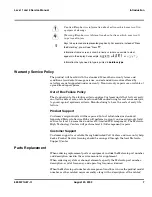
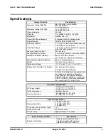
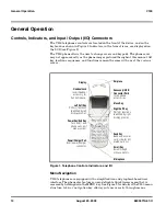
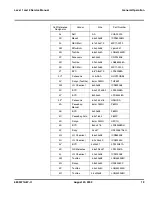
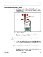
Controls, Indicators, and Input / Output (I/O) Connectors
The V150 telephones’ controls are located on the front of the device, and on the
keyboard as shown in Figure 1. Indicators, in the form of icons, are displayed on
the LCD (see Figure 2).
The V150 phone allows the user to change covers and keypads. The phone cover
may not appear exactly as the phone images pictured throughout this manual. All
key locations, sequences, and functions remain the same with any of the various
covers.
.
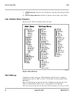
Menu Navigation
V150 telephones are equipped with a simplified icon and graphical-based user
interface. The phone also features a user-definable Quick Access menu that is
accessed by holding down the MENU key. See Figure 3 for details of theV150 menu
structure. A 4-way navigation key allows you to move easily through menus.
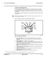
Figure 1. Telephone Controls, Indicators, and I/O
Earpiece
Headset Jack
Insert headset
accessory for
hands-free use.
Display
Microphone
Accessory/USB
Connector Ports
Insert phone
accessories.
Right Soft Key
Perform functions
identified by right
display prompt.
Menu Key
Power Key/End Key
Turn on/off, end
phone calls, exit
menu system.
Scroll Key
Scroll through
menus and lists.
Left Soft Key
Perform functions
identified by left
display prompt.
Send Key
Send and answer
calls, view recent
dialed calls list.
Power/Charger Port
Insert power/charger
connector.
Summary of Contents for V150
Page 1: ...Level 1 and 2 Service Manual V150 Dual Band Wireless Telephone GSM 900 DCS 1800MHz with GPRS ...
Page 2: ......
Page 4: ...4 August 20 2003 V150 ...
Page 22: ...22 August 20 2003 6809471A67 O General Operation V150 ...
Page 52: ...Index 4 February 13 2001 6809471A67 O V150 ...
Page 53: ......