


3-14
Amplifier Setup
SLE*-* Installation and Operation Manual
PRELIMINARY - Motorola Internal Use Only
Powering and Surge Protection
In conventional applications, the SLE*-* is powered through the input port.
CAUTION!
To avoid damage to the hybrids, it is recommended that you remove the input pad (JXP-IN) before you apply power to
the SLE*-*.
A 20-ampere, blade-type fuse is furnished in the amplifier module and provides over-current
protection for AC power applied to the input. You can power the SLE*-* from the output without
passing power through to the input port. To block power from the input port, remove the
power-block jumper illustrated in Figure 2-8.
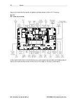
Figure 3-7 illustrates the location of the fuses in the SLE*-*:
Figure 3-7
SLE*-* fuses
F2
F1
Fuse
C A U TION : C ON TA INS PA R TS A N D
A SSE M B LIES S US CE PT IBL E T O
D A M AG E B Y E LE C TR O STAT IC
D IS C HA R G E ( ESD )
CHECK VOLTAG E
SE LECTOR
REFER TO MANUAL
AC
TEST
POINT
RTN EQ
JXP IN
JXP OUT
LPF
LPF
ICS
DC
AC
POWER PORT
FUSE
FUSE 1
SP
ADJ
JXP
JXP MID
JXP IN
FUSE 2
+24 DC
TEST PORT
STATUS
MONITOR
STATUS
MONITOR
MAN
ADJ
ADJ
ADU
RCB87
FWD EQ
LDR BD
EATT
-20 dB
-20 dB
H
H
L
L
-20 dB
-20 dB
-16 dB
RF IN
0
0
0
0
0
0
0
RF OUT2
RF OUT1
REFER TO
MANUAL FOR
FUSE VALUES
MGC
AUTO
R1
R2
R3
R4
C1
C2
C3
C6
C8
P1
P2
P4
P3
WARNING!
To avoid possible injury to personnel or damage to the equipment, remove 60/90 volt AC power from the system
before you remove any components from the housing.
The SLE*-* is shipped from the factory configured for 38 through 90 VAC powering as described
in Section 2, “Overview.”


