June, 2000
68P81124E57-A
5
Antenna Test/Fine Tuning
Mobile Gain Antennas
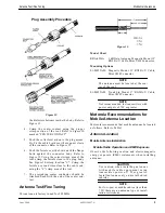
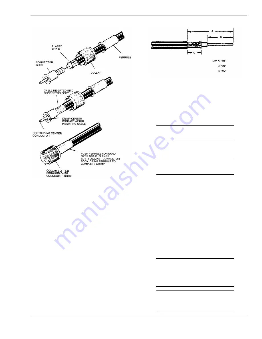
the dielectric bottoms inside the body. Refer to
Figure 12.
4.
Crimp the center contact using the proper
crimp section of the tool. Refer to Figure 10
marked “CENTER CONTACT”.
5.
Push the collar forward onto the plug assem-
bly. Fit the cable braid over the support sleeve
of the connector. Refer to Figure 12.
6.
Push the ferrule over the braid until the flange
butts against the connector body. Refer to
Figure 12. Using the correct crimp area of the
tool, crimp the ferrule close to the plug body.
See Figure 10 crimp location "C". Crimp the
ferrule a second time close to the cable end,
using the “C” crimp area of the tool.
7.
The protruding center conductor should be
trimmed flush with the end of the center con-
tact.
Antenna Test/Fine Tuning
This antenna is factory tuned for 902 MHz.
Model Chart
RRA-4936A
3 dB Gain Antenna, Magnetic Mount 12’
RG58A/U Cable, Mini UHF Connector
Mounting Options
01-80355A80
Magnetic Mount 12’ RG58A/U Cable,
Mini UHF Connector
NOTE
The antenna must be located at the cen-
ter of the roof.
01-80355A88
Trunk Lip Mount 17’ RG58A/U Cable,
Mini UHF Connector
NOTE
Not recommended for transmitters with
power outputs of 7 W or greater.
Motorola Recommendations for
Mobile Antenna Location
Motorola recommends that mobile antennas be located
as follows. Refer to Table 1.
Antenna Location
Mobile Antenna Installation
Mobile Radio Operation and EME Exposure
Observe the following caution and electromagnetic
energy exposure (EME) statements when installing
antennas:
CAUTION
Use caution when installing antennas
with mobile radio equipment using
transmitter power of 7 W or greater.
Install antennas only on metal bodied
vehicles.
NOTE
For low-power mobile radios (less than
7 W) there are no antenna type or instal-
lation restrictions.
Figure 12.
Plug Assembly Procedure
Figure 13.


