


26
603 Hardware Specifications
Loctite Corporation
860-571-5100
1001 Trout Brook Crossing
Rocky Hill, CT 06067
AI Technology (e.g., EG7655)
609-882-2332
1425 Lower Ferry Rd
Trent, NJ 08618
The following section provides a heat sink selection example using one of the commercially available heat
sinks.
1.8.6.3 Heat Sink Selection Example
For preliminary heat sink sizing, the die-junction temperature can be expressed as follows:
T
j
= T
a
+ T
r
+ (
θ
jc
+
θ
int
+
θ
sa
) * P
d
Where:
T
j
is the die-junction temperature
T
a
is the inlet cabinet ambient temperature
T
r
is the air temperature rise within the computer cabinet
θ
jc
is the die junction-to-case thermal resistance
θ
int
is the adhesive or interface material thermal resistance
θ
sa
is the heat sink base-to-ambient thermal resistance
P
d
is the power dissipated by the device
During operation the die-junction temperatures (T
j
) should be maintained less than the value specified in
Table 2. The temperature of the air cooling the component greatly depends upon the ambient inlet air
temperature and the air temperature rise within the electronic cabinet. An electronic cabinet inlet-air
temperature (T
a
) may range from 30 to 40
°
C. The air temperature rise within a cabinet (T
r
) may be in the
range of 5 to 10
°
C. The thermal resistance of the thermal interface material (
θ
int
) is typically about
1
°
C/W. Assuming a T
a
of 30
°
C, a T
r
of 5
°
C a CQFP package
θ
jc
= 2.2
°
C/W, and a power consumption
(P
d
) of 3.0 W, the following expression for T
j
is obtained:
Die-junction temperature: T
j
= 30
°
C + 5
°
C + (2.2
°
C/W + 1.0
°
C/W + R
sa
) * 3.0 W
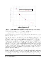
For a Thermalloy heat sink #2328B, the heat sink-to-ambient thermal resistance (R
sa
) versus airflow
velocity is shown in Figure 16.


