background image

Installation Guide

17

3.2 Gigabit Ethernet Ports

All NX series platforms have (2) RJ-45 Gigabit Ethernet uplink ports and (1) expansion module kit (optional). The
NX-4524 and NX-6524 models also have (24) RJ-45 Gigabit Ethernet switch ports. Motorola Solutions
recommends using Category 6 Ethernet cable for connections to the RJ-45 ports.

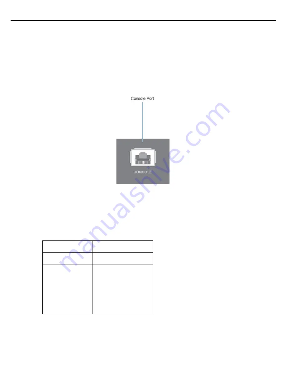
3.2.1 Console Port Setup

To add an NX series platform to the network using the

Command Line Interface

(CLI):

1.

Using the supplied console cable, connect the serial port to an RS-232 (DB-9) serial port on a separate
computer (the “configuration computer”).

2.

On the configuration computer, configure a terminal emulation application (such as HyperTerminal) as
follows:

3.

Apply power to the platform.

4.

Login when the prompt is displayed in the terminal window.

Terminal Type

VT 100

Port

COM port

Terminal Settings

19200bps transfer rate
8 data bits
no parity
1 stop bit
no flow control
no hardware compression

Summary of Contents for NX-4500 Series

Page 1: ...Motorola Solutions NX 4500 NX 4524 NX 6500 NX 6524 Series Integrated Services Platform Installation Guide ...

Page 2: ...2 NX 4500 NX 6500 Series Intregrated Services Platform MOTOROLA SOLUTIONS and the Stylized M Logo are registered in the US Patent Trademark Office Motorola Solutions Inc 2013 All rights reserved ...

Page 3: ...1 System Status LEDs 11 2 5 2 Fan Status LED 12 2 5 3 Temperature Status LED 12 2 6 RJ 45 Giganbit Ethernet LEDs 13 2 6 1 Uplink Port LEDs 13 2 6 1 1 RJ 45 Port Speed LED Uplink Ports UP1 UP2 13 2 6 1 2 RJ 45 Port Status LED Uplink Ports UP1 UP2 13 2 6 2 Switch Ports 14 2 6 2 1 RJ 45 Port Speed LED Switch Ports GE1 GE24 14 2 6 2 2 RJ 45 Port Status LED Switch Ports GE1 GE24 14 3 0 Hardware Setup 1...

Page 4: ...Integrated Services Platform 21 3 2 6 Verifying the Installation 21 4 0 Basic Configuration 22 5 0 Regulatory Information 32 5 1 Radio Frequency Interference Requirements FCC 32 5 2 Statement of Compliance 33 5 3 Waste Electrical and Electronic Equipment WEEE 34 5 3 1 Turkish WEEE Statement of Compliance 35 6 0 Motorola Solutions Support Center 36 7 0 NX 4500 NX 6500 Series China RoHS Compliance 3...

Page 5: ... Port Connector NX 6500 Integrated Services Platform NX 6524 Integrated Services Platform with 24 Port Connector This document is written for the professional installer deploying the NX series integrated services platform 1 1 Unpacking Verify that you have the equipment listed below NX series platform Console cable Rack mounting brackets NX Series Integrated Services Platform Installation Guide th...

Page 6: ...recommends the use of an Uninterruptible Power Supply UPS that supports the NX 4500 NX6500 series platform power rating Not using a UPS can result in data loss or equipment damage due to a power surge or power failure Verify that the power connector and socket are accessible at all times during the operation of the equipment Do not work with power circuits in dimly lit spaces Do not install this e...

Page 7: ...want to link and near a power outlet Maintain a tempurature range within 40 to 149 F 40 to 65 C and humidity range within 10 to 90 non condensing Provide adequate space approximately 2 inches on all sides for proper air flow Confirm access for installing cabling and maintaining all devices Install the switch unit so that status LEDs are clearly visible Ensure that twisted pair cables are always ro...

Page 8: ...8 NX 4500 NX 6500 Series Intregrated Services Platform ...

Page 9: ... NX 6500 19lb 8 618kg NX 4524 NX 6524 23lb 10 433kg Operating temperature 32 F to 104 F 0 C to 40 C Operating humidity 5 to 85 RH non condensing Operating altitude Maximum 10 000ft 40 C 15 RH Storage temperature 40 F to 158 F 40 C to 70 C Storage humidity 5 to 85 RH non condensing Storage altitude Maximum 30 000 ft 12 C 15 RH AC input voltage 90 264VAC 50 60Hz PoE power output 360W maximun only ap...

Page 10: ...cal contractors are familiar with wiring for data processing equipment and can help with the load balancing of these circuits Install surge protection Be sure to use a surge protection device between the electricity source and the NX series platform Install an Uninterruptible Power Supply UPS A UPS provides continuous power during a power outage Some UPS devices have integral surge protection UPS ...

Page 11: ...itializing Green Solid Green Blinking OS loading Green Amber Blinking Green Amber Blinking OS boot error Green Solid Off After AP adoption final ready state Green Solid Green Solid OS boot success normal operation active adopting Green Blinking Green Solid Redundant system failover Green Blinking Green Amber Blinking Redundant system no failover Green Solid Amber Blinking Software configuration er...

Page 12: ...ture limit System will be held in reset until the issue is resolved TEMP LED Event Off System off Green Solid Ambient inlet temperature is within specified operating temperature limit Amber Solid Ambient inlet temperature is near the maximum operating temperature limit During start up this LED is lit solid amber This is normal behavior and does not indicate an error Amber Blinking Ambient inlet te...

Page 13: ...ng sections decode the combinations of LED colors and states for the Uplink Ports and Switch Ports LEDs 2 6 1 Uplink Ports LEDs 2 6 1 1 RJ 45 Port Speed LED Uplink Ports UP1 UP2 2 6 1 2 RJ 45 Port Status LED Uplink Ports UP1 UP2 Port Speed LED Event Off 10 Mbps Amber Solid 100 Mbps Green Solid 1000 Mbps Port Activity LED Event Off No link or port disabled Green Solid Link present Green Blinking Ac...

Page 14: ...eed LED Event Off 10 Mbps Amber Solid 100 Mbps Green Solid 1000 Mbps Amber Blinking Port Fault Port Activity LED Event Off No link or port disabled Green Solid Link present Green Blinking Activity transmit and receive Amber Solid MSTP on port are not in forwarding state Amber Blinking Link fault error frames can affect connectivity and errors are monitored for a link fault indication ...

Page 15: ...he front chassis 2 RJ 45 Gigabit Ethernet Ports 1 RJ 45 Serial Console Port 4 USB Ports Host 2 0 24 RJ 45 Gigabit Ethernet Port Connector NX 4524 NX 6524 only The following figure represents the front of the NX 4500 and NX 6500 models The following figure represents the front of the NX 4524 and NX 6524 models ...

Page 16: ...USB ports The above diagram shows each port and the cables or devices attached to them The sections that follow describe detailed connection and cabling information for each port For software configuration please see the current WiNG System Reference Guide available from the Motorola Solutions website at http supportcentral motorolasolutions com support product manuals do ...

Page 17: ...d an NX series platform to the network using the Command Line Interface CLI 1 Using the supplied console cable connect the serial port to an RS 232 DB 9 serial port on a separate computer the configuration computer 2 On the configuration computer configure a terminal emulation application such as HyperTerminal as follows 3 Apply power to the platform 4 Login when the prompt is displayed in the ter...

Page 18: ...lash storage devices to the platform The sever can use the USB flash storage device for file transfers and firmware updates Complete the setup instructions to connect devices and access the devices through the Web UI or Command Line Interface 1 Connect the USB flash drive to the USB port on the front of the platform 2 Set the computer to use an IP address between 192 168 0 10 and 192 168 0 250 on ...

Page 19: ...in the expansion module 3 Connect the power cables to the PCIe card 4 pin connector if required 4 Install PCIe blanks into any unused slots in the expansion module Width 5 95in 151 1mm Height 3 16in 80 4mm Depth 5 39in 136 9mm Weight 0 80lb 0 3629kg Total power limit 3 3VDC 3 0A maximum Total power connector limit 5 0VDC 2 0A maximum Total PCIe slot power limit 12 0VDC 5 0A maximum WARNING NX Seri...

Page 20: ...curity torque screwdriver tighten the two screws on the sides of the expansion module to 5 0 lbf in The following figure represents the installation of the expansion module for NX 4524 and NX 6524 models 3 2 4 Rack Mount Instructions To install an NX series platform in a rack 1 Attach the rack mounting brackets to the platform 2 Attach the mounting brackets to the rack using screws appropriate for...

Page 21: ...nect an approved power cable to the connector on the back of the platform and plug it into a standard AC outlet with a voltage range of 100 to 240 VAC 3 2 6 Verifying the Installation View the LEDs on the front panel of the platform to ensure the device is functioning properly For more information on LED patterns see LED Codes on page 11 ...

Page 22: ... with a working Web browser Set the computer to use an IP address between 192 168 0 10 and 192 168 0 250 on the connected port Set a subnet network mask of 255 255 255 0 2 Once the computer has an IP address point the Web browser to https 192 168 0 1 The following login screen displays 3 Enter the default username admin in the Username field 4 Enter the default password motorola in the Password fi...

Page 23: ... uses the default parameters for most of the configuration parameters and sets up a working network with the least amount of manual configuration The Advanced Setup wizard is for administrators who prefer more control over the different configuration parameters A few more configuration screens are available for customization when the Advanced Setup wizard is used The first page of the Initial Setu...

Page 24: ...r of changes to the Access Point s default configuration For information on using the Access Point s Advanced Setup option refer to the WiNG Access Point System Reference Guide to familiarize yourself with the feature set supported by the WiNG operating system The guide is available at http supportcentral motorolasolutions com support product manuals do To configure the Access Point using the Typi...

Page 25: ...critical task while configuring the Access Point as it defines the correct channels of operation and ensures compliance to the regulations of the selected country This field is only available for the Typical Setup Wizard 12 Select Next to set the Access Point s network mode NOTE If wanting to adopt the Access Point to a controller or service platform use the controller or service platform s reside...

Page 26: ...ecommended in a deployment supported by just a single Access Point Bridge Mode In Bridge Mode the Access Point depends on an external router for routing LAN and WAN traffic Routing is generally used on one device whereas bridging is typically used in a larger density network Select Bridge Mode when deploying this Access Point with numerous peer Access Points supporting clients on both the 2 4GHz a...

Page 27: ...selecting this option define the following DHCP Server and Domain Name Server DNS resources as those fields will become enabled on the bottom portion of the screen Use on board DHCP server to assign IP addresses to wireless clients Select the checkbox to enable the Access Point s DHCP server to provide IP and DNS information to clients on the LAN interface Range Enter a starting and ending IP Addr...

Page 28: ...SID Configure the SSID for the WLAN WLAN Type Configure the encryption and authentication to use with this WLAN No Authentication and No Encryption Configures a network without any authentication This option also configures the network without encryption This means that any data transmitted through the network is in plain text Any device between end points can see the information transmitted This ...

Page 29: ...e RADIUS Server Configuration screen if required Otherwise the Typical Setup Wizard displays the Summary and Commit screen 20 Use the Radius Server Configuration screen to configure the users for the onboard RADIUS server Use the screen to add modify and remove RADIUS users ...

Page 30: ...seandaddanotheruser selectCreate Tocreatetheentry in the RADIUS server database and close the Add User dialog select Create Close 24 Select Modify User on the RADIUS Server Configuration screen to modify information for an existing user from the RADIUS database Highlight the user entry then select Modify User 25 Select Delete User on the RADIUS Server Configuration screen to remove information for...

Page 31: ...before it s deployed However if a screen displays settings not intended as part of the initial configuration then any screen can be selected again from within the Navigation Panel and its settings modified accordingly If the configuration displays as intended select Save Commit to implement these settings to the Access Point s configuration If additional changes are warranted based on the summary ...

Page 32: ...armful interference when the equipment is operated in a commercial environment This equipment generates uses and can radiate radio frequency energy and if not installed and used in accordance with the instruction manual may cause harmful interference to radio communications Operation of this equipment in a residential area is likely to cause harmful interference in which case the user will be requ...

Page 33: ...hat this device is in compliance with all the applicable Directives 2004 108 EC and 2006 95 EC A Declaration of Conformity may be obtained from http www motorolasolutions com doc Japan Voluntary Control Council for Interference VCCI Class A ITE Chinese Altitude and Humidity Declarations ...

Page 34: ...UE todos os produtos no fim de vida devem ser devolvidos à Motorola Solutions para reciclagem Para obter informações sobre como devolver o produto visite http www motorolasolutions com recycling weee Nederlands Voor klanten in de EU alle producten dienen aan het einde van hun levensduur naar Motorola Solutions te worden teruggezonden voor recycling Raadpleeg http www motorolasolutions com recyclin...

Page 35: ... la Motorola Solutions pentru reciclare Pentru informaţii despre returnarea produsului accesaţi http www motorolasolutions com recycling weee Slovenski Za kupce v EU vsi izdelki se morajo po poteku življenjske dobe vrniti podjetju Motorola Solutions za reciklažo Za informacije o vračilu izdelka obiščite http www motorolasolutions com recycling weee Slovenčina Pre zákazníkov z krajín EU Všetky výro...

Page 36: ... limits set forth in support agreements If you purchased your product from a Motorola Solutions business partner contact that business partner for support Customer Support Web Sites The Motorola Solutions Support Central Web site located at http supportcentral motorolasolutions com provides information and online assistance including developer tools software downloads product manuals and online re...

Page 37: ...Installation Guide 37 7 NX 4500 NX 6500 Series China RoHS Compliance ...

Page 38: ...38 NX 4500 NX 6500 Series Intregrated Services Platform ...

Page 39: ...Installation Guide 39 ...

Page 40: ...MOTOROLA MOTO MOTOROLA SOLUTIONS and the Stylized M Logo are trademarks or registered trademarks of Motorola Trademark Holdings LLC and are used under license All other trademarks are the property of their respective owners 2013 Motorola Solutions Inc All Rights Reserved MN000264A01 Revision A October 2013 ...

Reviews: