Chapter 3
Vehicle Preparation
3.1
General Guidelines for Radio Installation
This product must be installed in a vehicle in accordance with the vehicle manufacturer guidelines and
the instruction detailed in this manual. Only the specified Motorola Solutions parts in this manual
should be used.
Failure to do so could result in non-compliance to the Automotive Directive (72/245/EEC, as amended
by 95/54/EC). For products fitted to two and three wheeled vehicles, Directive 97/24/EC applies.
This radio is only designed and certified to be used for terrestrial use only.
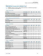
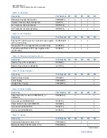
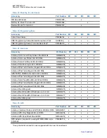
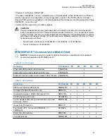
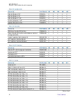
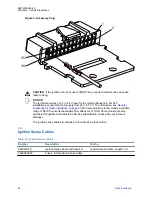
An accessory connector on the rear of the radio enables you to attach different accessories (see
section “Accessory Connection Plan”).
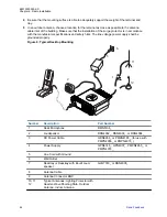
A mobile microphone port on the front control head panel provides for the connection of various types
of microphones.
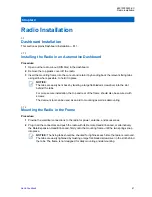
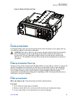
You can install the radio in a vehicle, using one of these methods:
• Using the direct mounting trunnion and power cables supplied with a standard radio package.
• Remote mounted in the car radio cut-out (using the required din mounting kit PMLN5094), per
ISO7736.
• Two types of the Remote Mount.
NOTICE:
This radio uses a standard 12 V power supply connection. In vehicles with 24 V power supply, a
DC/DC converter is required. Use only DC/DC converter vendors, who provide a certification for
vehicle installation and meet radio Power Supply specification. Motorola Solutions recommends
a suitable range of DC/DC converters available from Alfatronix LTD UK. Some models are also
available through Motorola Solutions Service Organization, check with your Account Manager.
Be aware when planning the installation that there is a maximum current consumption of 4.5 A
during PTT and up to 30 mA (non-Ethernet)/ 90 mA (Ethernet) when the radio is switched off.
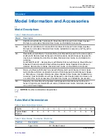
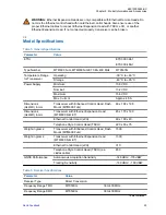
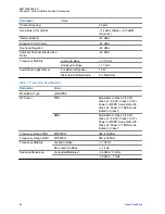
For Power Supply specification, see
Model Specifications on page 23
The radio should be mounted horizontally near the driver, so the driver can easily view, access, and
operate the controls, microphone (location of the microphone clip), and other accessories. Before
installation, consider the following factors:
• Ensure that the location for the radio installation is not exposed to dirt and moisture.
• Verify that the space around the mobile unit is sufficient for air flow and installation.
• Check that there is enough routing space for the power cable connector and the antenna coaxial
cable.
• To minimize pinching, crushing, and overheating of wires and cables, plan the best place to run
connections.
• In a vehicle with an airbag, make sure that the mounting location of the radio, or of any radio
accessory, is not in the deployment path of the air bag.
68015000553-KC
Vehicle Preparation
35
Summary of Contents for MTM800 FuG ET
Page 2: ......
Page 4: ...This page intentionally left blank ...
Page 8: ...This page intentionally left blank ...
Page 12: ...This page intentionally left blank ...
Page 15: ...Table 73 Fuse Identification 131 68015000553 KC List of Tables Send Feedback 15 ...
Page 16: ...This page intentionally left blank ...
Page 18: ...This page intentionally left blank ...
Page 34: ...This page intentionally left blank ...
Page 126: ...This page intentionally left blank ...
Page 130: ...This page intentionally left blank ...
Page 132: ...This page intentionally left blank ...
Page 134: ...This page intentionally left blank ...
Page 138: ...Diese Seite wurde absichtlich leer gelassen ...
Page 142: ...Diese Seite wurde absichtlich leer gelassen ...
Page 146: ...Diese Seite wurde absichtlich leer gelassen ...
Page 148: ...Diese Seite wurde absichtlich leer gelassen ...
Page 220: ...Diese Seite wurde absichtlich leer gelassen ...
Page 250: ...Diese Seite wurde absichtlich leer gelassen ...
Page 260: ...Diese Seite wurde absichtlich leer gelassen ...
Page 264: ...Diese Seite wurde absichtlich leer gelassen ...
Page 266: ...Diese Seite wurde absichtlich leer gelassen ...

