background image

6809501A48-A

           November 03, 2006  

21

Level 1 and 2 Service Manual

Disassembly

Removing and Replacing the Rear Housing


1.

Remove the battery cover, battery, and memory card as described in the 
procedures.


2.

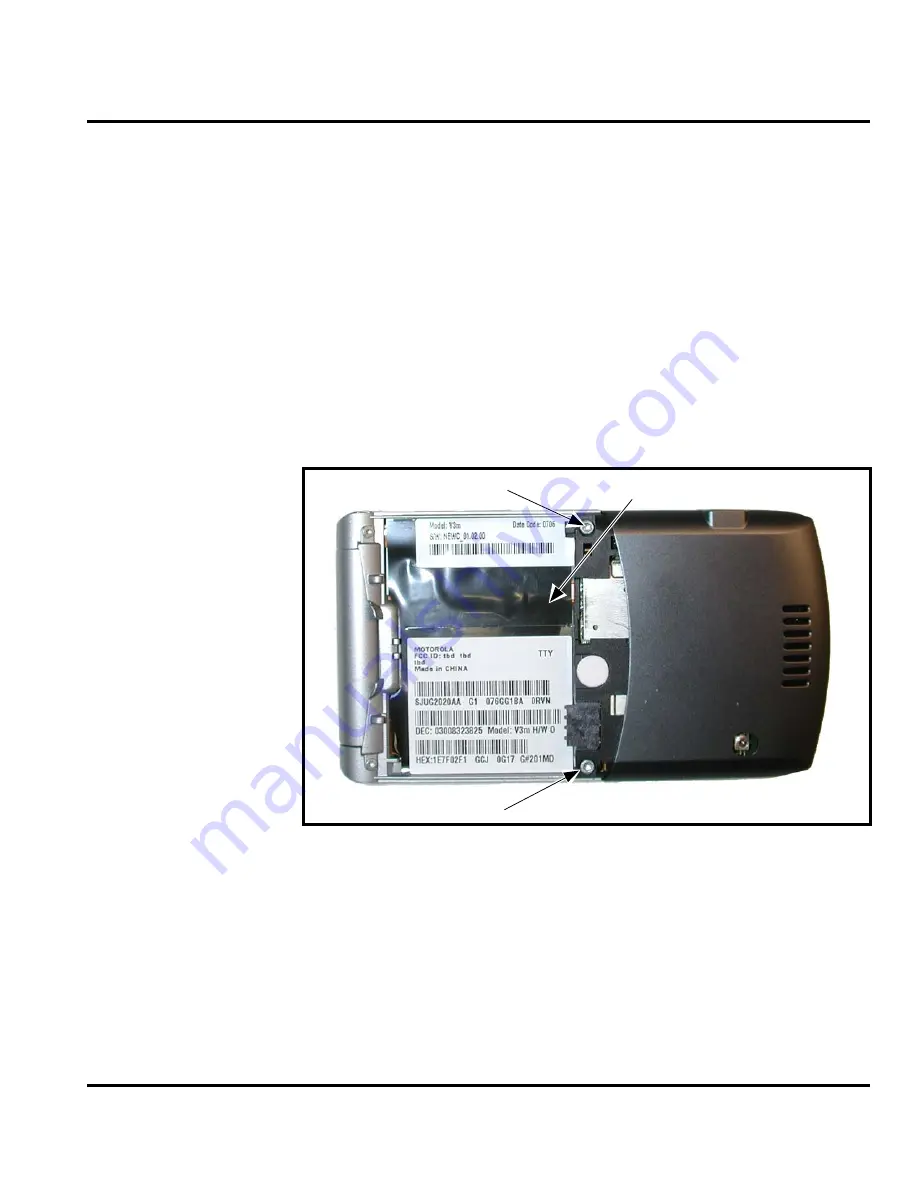
Using a Torx driver with a T-6 bit, remove the screws at each side of the phone. 
Retain the screws for reassembly. See Figure 4.

G

This product contains static-sensitive devices. Use anti-static handling procedures 
to prevent electrostatic discharge (ESD) and component damage.

G

In addition to 2 screws, the rear housing assembly is fastened with plastic latches. 
These are fragile and should be released with care.


051343o

Figure 4. Removing the Rear Housing Screws

Screw

Battery Insulator

Screw

Summary of Contents for MOTORAZR V3M

Page 1: ...Level 1 and 2 Service Manual 6809501A48 A V3m Digital Wireless Telephone CDMA 1900 MHz CDMA 800 MHz ...

Page 2: ... service names are the property of their respective owners The Bluetooth trademarks are owned by their proprietor and used by Motorola Inc under license Motorola Inc 2006 All rights reserved Mobile Devices Business Sawgrass International Concourse 789 International Parkway Room S2C Sunrise FL 33325 6220 ...

Page 3: ...8 Removing and Replacing the Battery Cover and Battery 18 Removing and Replacing the Memory Card 20 Removing and Replacing the Rear Housing 21 Removing and Replacing the Antenna 25 Removing and Replacing the Transceiver Board Assembly 27 Removing and Replacing the Flip Assembly Cover and CLI Lens 28 Removing and Replacing the Camera Assembly 37 Removing and Replacing the Display Module Assembly 38...

Page 4: ...4 November 03 2006 6809501A48 A Contents V3m ...

Page 5: ...re identified by the model number on the housing Use the entire model number when inquiring about the product Numbers are also assigned to chassis and kits Use these numbers when requesting information or ordering replacement parts Product Names Product names are subject to change without notice Some product names as well as some frequency bands are available only in certain markets Regulatory Age...

Page 6: ...r programs with the Motorola product About this Service Manual Using this service manual and the suggestions contained in it assures proper installation operation and maintenance Refer questions about this manual to the nearest Customer Service Manager Audience This service manual aids service personnel in testing and repairing V3m telephones Service personnel should be familiar with electronic as...

Page 7: ...Motorola Service Hubs will perform warranty and non warranty field service for level 2 assemblies and level 3 limited PCB component The Motorola High Technology Centers will perform level 4 full component repairs Customer Support Customer support is available through dedicated Call Centers and in country help desks Product Service training is available through the local Motorola Support Center Par...

Page 8: ...ment parts test equipment and manuals from AAD U S A Outside U S A Phone 800 814 0601 Phone 847 538 8023 FAX 800 622 6210 FAX 847 576 3023 Website http businessonline motorola com EMEA Phone 49 461 803 1404 Website http emeaonline motorola com Asia Phone 65 648 62995 Website http asiaonline motorola com ...

Page 9: ...rating Temperature Range 30 C to 60 C 22 F to 140 F Humidity 80 Relative Humidity at 50 C 122 F Battery Life 740 mAh Li Ion Battery Digital Talk Time 180 Minutes for 740mAh and IS95 IS2000 Cell PCS CDG Suburban Profile with 40 VAF 110 6dBm Digital Standby Time 195 Hours IS95 IS2000 Cell PCS Slot Cycle 1 All talk and standby times are approximate and depend on network configuration signal strength ...

Page 10: ...ra module is a 1 3 mega pixel VGA CMOS camera The main housing assembly includes a battery cover chassis main circuit board keypad plastic front housing and internal antenna The main circuit board contains the Receiver Transmitter Synthesizer and Control Logic Circuitry which together comprise the dual band tri mode phone electronics The telephones are made of polycarbonate plastic The display and...

Page 11: ...e on the phone in all lan guages Tap Press a key to generate a character Numeric The keypad produces numeric characters only For some text areas this is the only method available for example phone numbers Caller Line Identification Upon receipt of a call the calling party s phone number is compared to the phone book If the number matches a phone book entry that name will be displayed If there is n...

Page 12: ...rm of icons are displayed on the LCD see Figure 2 V3m phones have an audible alert transducer at the bottom and I O connectors consisting of a charger accessory port located on the side of the phone See Figure 1 Soft keys refer to non labeled keys that correspond to text options displayed on the screen The left and right soft keys perform the function shown in the corners 051355o 051356o Figure 1 ...

Page 13: ...rogress Signal Strength Indicator Shows the strength of the phone s connection with the network Calls cannot be sent or received when the no signal indica tor is displayed Roam Indicator Appears when the phone uses another network system out side the user s home network When leaving the home network area the phone roams or seeks another network Message Waiting Indicator Appears when the phone rece...

Page 14: ... 2 Appears when a voicemail message is received This is a network dependent feature menu Alert Setting Indicator Shows the current selected alert The default alert setting is a ringer GPS Indicator Shows when your phone can send location information or not 2 Network subscription service provider dependent feature Not available in all areas ...

Page 15: ...6809501A48 A November 03 2006 15 Level 1 and 2 Service Manual General Operation User Interface Menu Structure Figure 3 shows the telephone menu structure 051357o 051360 Figure 3 Menu Structure ...

Page 16: ...ry Removal Removing the battery causes the device to immediately shut down and any pending work for example partially entered phone book entries or outgoing messages is lost Operation For detailed operating instructions refer to the appropriate User s Guide listed in the Related Publications section toward the end of this manual Pressing either volume key will mute the alert To ensure proper memor...

Page 17: ...6 80387A95 antistatic mat 66 80334B36 ground cord and 42 80385A59 wrist band Provides protection from damage to device caused by electrostatic discharge ESD 0 00 00 30005 Disassembly tool plastic with flat and pointed ends manual opening tool from AMS Used during assembly disassembly of device Tweezers plastic Used during assembly disassembly Digital Multimeter HP34401A2 Used to measure battery vo...

Page 18: ...mage from electrostatic discharge ESD Ensure adequate static protection is in place when handling shipping and servicing the internal components of this equipment G Avoid stressing the plastic in any way to avoid damage to either the plastic or internal components E All batteries can cause property damage and or bodily injury such as burns if a conductive material such as jewelry keys or beaded ch...

Page 19: ...into the battery compartment and push down followed by the opposite edge of the battery 7 Insert the bottom edge of the of the battery cover into the rear housing then push the top edge of the cover down and snap it into place 060658o Figure 2 Removing the battery E There is a danger of explosion if the Lithium Ion battery is replaced incorrectly Replace only with the same type of battery or equiv...

Page 20: ... as described in the procedures 2 Slide the memory card out of the memory card slot as shown in Figure 3 3 To replace slide the memory card contacts facing down all the way into the memory card slot 4 Replace the battery and the battery cover as described in the procedures 060658o Figure 3 Removing the Memory Card Memory card ...

Page 21: ...he screws at each side of the phone Retain the screws for reassembly See Figure 4 G This product contains static sensitive devices Use anti static handling procedures to prevent electrostatic discharge ESD and component damage G In addition to 2 screws the rear housing assembly is fastened with plastic latches These are fragile and should be released with care 051343o Figure 4 Removing the Rear Ho...

Page 22: ... V3m 3 Use the plastic tweezers to remove the battery insulating material on the right side of the battery compartment Do not reuse the battery insulating material for reassembly 051343o Figure 5 Removing the Rear Housing Screws Battery Insulator ...

Page 23: ...ointed end of the plastic disassembly tool into the openings on the rear housing 5 Carefully rotate the rear housing away from the front housing and flip assembly 051344o Figure 6 Removing the Rear Housing Latches 060662o Figure 7 Removing the Rear Housing Assembly Latches Latches Display flex connector Keypad flex connector ...

Page 24: ...n gently press down on the flex connector until it is properly seated in it s socket 10 Rotate the rear housing assembly so it sits over the phone 11 Align the housing latches with the corresponding openings on the front housing Gently press the housings together until the catches snap into place 12 Cover the display flex with new battery insulator material Do not reuse the old battery insulating ...

Page 25: ...ve the battery cover battery and rear housing assembly as described in the procedures 2 Use the metal tweezers to grasp the rubber antenna grommets and carefully remove them from the antenna assembly See Figure 8 Set the rubber grommets aside for reuse 051346o Figure 8 Removing the Antenna Grommets Tweezers Grommets ...

Page 26: ...embly to the phone 6 Carefully press the antenna assembly into position starting from the left side until the antenna assembly latches snap into position 7 Reinstall the rubber antenna assembly grommets into their slots Each antenna grommet is uniquely shaped to fit into its respective position 8 Replace the rear housing assembly battery and battery cover as described in the procedures 060663o Fig...

Page 27: ...ool See Figure 10 3 To replace insert the transceiver board assembly into the rear housing 4 Carefully and gently press the transceiver board into position and until it snaps into place 5 Replace the antenna assembly rear housing battery and battery cover as described in the procedures G This product contains static sensitive devices Use anti static handling procedures to prevent electrostatic dis...

Page 28: ...mbly as described in the procedures 2 Remove the 4 flip assembly screw caps 3 Use the T 5 driver to remove the 4 screws from the flip assembly see Figure 11 Retain the screws for re assembly 4 Before removing the flip cover note the locations of the smart buttons on the sides of the flip assembly 051349 051350o Figure 11 Removing the Flip Assembly Screws Screw Caps Screw Caps Screws Screws ...

Page 29: ...move the smart buttons on the side of the flip assembly Set them aside for reassembly 7 Lift the flip cover away from the flip assembly Be careful not to damage the display flex cable 8 Slide the flat end of the plastic disassembly tool between the lens and the metal frame 051351o Figure 12 Separating the Flip Assembly Cover Flip Cover Disassembly Tool ...

Page 30: ...bly tool by 90 see Figure 13 10 Carefully lift up the CLI Lens from the display module assembly 11 Carefully use the plastic tool remove any remaining glue 062020o Figure 13 CLI Lens Removal G Do not use any kind of liquid or spray to remove the remaining glue CLI lens Disassembly tool ...

Page 31: ... the CLI lens to the opening Ensure that the liner is overlapping the inside surface The CLI lens fits in one direction only see Figure 14 13 Expose the adhesive surface of the new CLI lens and attach the replacement CLI lens to the flip outer assembly 062026o Figure 14 CLI Lens Replacement Flip outer assembly CLI lens liner facing up ...

Page 32: ...November 03 2006 6809501A48 A Disassembly V3m 14 Align CLI lens to the flip outer assembly and lightly press the low tech film around the CLI opening see Figure 15 062027o Figure 15 Flip CLI Lens Placement ...

Page 33: ...ember 03 2006 33 Level 1 and 2 Service Manual Disassembly 15 Align the top left and right sides of the flip cover and press into position see Figure 16 062028o Figure 16 Flip Cover Replacement Top Left and Right Sides ...

Page 34: ...34 November 03 2006 6809501A48 A Disassembly V3m 16 Apply pressure at the corners of the CLI Lens for 3 seconds to insure good adhesion see Figure 17 062032o Figure 17 Flip CLI Lens Replacement ...

Page 35: ...06 35 Level 1 and 2 Service Manual Disassembly 17 Insert and tighten the 4 screws to 1 5 in lbs to secure the flip cover to the flip assembly Avoid damage to the flex cable see Figure 18 062040o Figure 18 Flip Screws Replacement ...

Page 36: ...18 Insert the 4 rubber screw caps over the flip assembly screws see Figure 19 19 Replace the transceiver board assembly rear housing antenna assembly battery and battery cover as described in the procedures 062041o Figure 19 Flip Screw Cap Replacement ...

Page 37: ...nd flex out of the flip assembly see Figure 20 4 To replace carefully press the camera assembly into its slot in the flip assembly 5 Insert the end of the camera assembly flex cable into its slot in the ZIF connector on the flip display assembly Avoid damage to the flex cable 6 Replace the flip assembly cover transceiver board rear housing antenna battery and battery cover as described in the proc...

Page 38: ...t the display module assembly flex connector from its socket see Figure 21 3 Carefully and gently lift one corner of the display module assembly out of the flip assembly 4 Avoid damage to the electrical components on the flex while carefully removing the display module assembly from the flip assembly G The flexible printed cable FPC flex is easily damaged Exercise extreme care when handling 051353...

Page 39: ...ip assembly Ensure that all of the display none of the display assembly components are damaged 8 align the flip display flex to the flex connector on the flip display assembly and gently press down on the flex connector until properly seated 9 Replace the camera assembly flip assembly cover transceiver board rear housing antenna battery and battery connector as described in the procedures Figure 2...

Page 40: ...p see Figure 23 2 Use the disassembly tool to unseat the display module assembly flex connector from its socket see Figure 24 062042o Figure 23 Lifting the Grounding Flip Boot Strap G The flexible printed cable FPC flex is easily damaged Exercise extreme care when handling 062000o Figure 24 Display Module Assembly Flex Connector Grounding Flip Boot Strap Flex connector ...

Page 41: ... 25 4 Carefully and gently lift one corner of the display module assembly out of the flip assembly see Figure 26 5 Avoid damage to the electrical components on the flex while carefully removing the display module assembly from the flip assembly 062001o Figure 25 Removing the Camera Assembly 062002o Figure 26 Removing the Display Module Assembly Camera Assembly Display Module assembly ...

Page 42: ...inge Assembly V3m 6 Carefully lift the display gasket from the assembly see Figure 27 7 Carefully lift the contact grounding hinge from the assembly see Figure 28 062043o Figure 27 Removing the Display Gasket 062044o Figure 28 Removing the Contact Grounding Hinge ...

Page 43: ...om the flip assembly see Figure 29 Retain the screws for reassembly Ensure the screws have thread lock 9 Remove the 2 end caps from the assembly flip Retain the end caps and grounding clip for reassembly see Figure 30 10 Use a small flat tip screwdriver to assist in disassembling the flip from the base housing 062045o Figure 29 Removing the Screw Caps 062006o Figure 30 Screw Caps Removed ...

Page 44: ... towards top see Figure 31 12 Rotate flip assembly away to disengage the hinge cam see Figure 32 062007o Figure 31 Hinge Cam Location 062008o Figure 32 Flip Assembly Removal G Ensure that display gasket and contact grounding hinge have been removed before continuing Failure to remove these parts may cause damage to the Hinge Cam and Hinge Grounding Clip Flip assembly ...

Page 45: ...placing the Hinge Assembly Removal of the Main Flex 13 Use the plastic tweezers to remove the battery insulating material on the right side of the battery compartment Do not reuse the battery insulating material for reassembly see Figure 33 062009o Figure 33 Flex Removal Part 1 ...

Page 46: ...gh the opening by the hinge area see Figure 34 Replacing the Flip Hinge Assembly 1 Carefully and gently slide the Main Flex though the opening by the hinge area see Figure 35 062010o Figure 34 Flex Removal Part 2 G The flexible printed cable FPC flex is easily damaged Exercise extreme care when handling ...

Page 47: ...006 47 Level 1 and 2 Service Manual Removing and Replacing the Hinge Assembly 2 Align main flex to the grove location for the main flex see Figure 36 062012o Figure 35 Flex Reinstall Part 1 062013o Figure 36 Flex Install Part 2 ...

Page 48: ...A48 A Removing and Replacing the Hinge Assembly V3m 3 Insert flip sleeve so that it is flush with flip inner surface see Figures 37 and 38 062014o Figure 37 Flip Sleeve Install Part 1 062014o Figure 38 Flip Sleeve Install Part 2 ...

Page 49: ...g the Hinge Assembly 4 Align flip housing to the front housing as shown see Figure 39 Note Ensure that the housing and flip are not binding the main flex 062014o Figure 39 Flip Hinge Alignment G The flexible printed cable FPC flex is easily damaged Exercise extreme care when handling ...

Page 50: ...ng the Hinge Assembly V3m 5 Use a small flat tip screwdriver to press in the hinge cam while pushing the hinge cam towards the cam opening see Figure 40 Ensure that all of the parts are aligned in the hinge area 062017 19o Figure 40 Flip Hinge Reassembly ...

Page 51: ... caps for the assembly flip Ensure that the end caps and grounding clip are assembled see Figure 41 7 Use the T 3 driver to install and tighten the 2 screws to a final torque setting of 9 6 Ncm 85 inch pounds Do not over tighten see Figure 42 062006o Figure 41 End Cap Reinstall 062005o Figure 42 Reinstalling the Screw Caps ...

Page 52: ...eplacing the Hinge Assembly V3m 8 Carefully install the contact grounding hinge to the assembly see Figures 43 and 44 062020o Figure 43 Reinstalling the Contact Grounding Hinge Part 1 062021o Figure 44 Reinstalling the Contact Grounding Hinge Part 2 ...

Page 53: ...y see Figure 45 10 Align the display module assembly to the flip assembly 11 Carefully lower the display module into the flip assembly Ensure that none of the display assembly components are damaged 062022o Figure 45 Reinstalling the Display Gasket G Ensure the display gasket is properly seated in the flip inner before installing the display module ...

Page 54: ...Figure 46 13 Insert the end of the camera assembly flex cable into its slot in the ZIF connector on the flip display assembly Avoid damage to the flex cable 14 Carefully insert switches into button cavities see Figure 47a and 47b 062046o Figure 46 Reinstalling the Display Assembly 062047o 062048o Figure 47 Replacing Switches in Button Cavities A B ...

Page 55: ... in the contact grounding flip boot strap see Figure 48 16 Insert Button Volume Control and Button VR see Figure 48 17 Replace the flip assembly cover transceiver board rear housing antenna battery and battery cover as described in the procedures 062049o Figure 48 Replacing the Contact Grounding Flip Boot Strap ...

Page 56: ...ion Each Motorola CDMA phone is labeled with a variety of identifying numbers Figure 49 describes the current identifying labels 020463o Figure 49 CDMA Telephone Identification Label MOTOROLA INC FCC ID IHDT5UV1 EE 3 CANADA 109 182 230A TYPE UVKA 832 2412 CHANNEL OPERATION SWF3001A H7 25821A2 VY SN D414AF0EYAA A56 G6 Mfg by Type approval information NAMPS info analog Transceiver model code 39 Tran...

Page 57: ...connected properly substitute a known good antenna If the fault is still present proceed to b b Transceiver board assembly defective Replace the transceiver board assembly refer to 1c Verify that the fault has been cleared and reassemble the unit with the new transceiver board assembly 3 Display is erratic or provides partial or no display a Transceiver board connections faulty Remove rear chassis...

Page 58: ...eiver board assembly 7 Phone does not sense when flip is opened or closed usually indicated by inability to answer incoming calls by opening the flip or inability to make outgoing calls a Flip assembly defective Temporarily replace the flip assembly with a known good assembly If fault has been cleared reassemble with the new flip assembly If fault not cleared proceed to b b Transceiver board assem...

Page 59: ...hnical support engineer for information about equipment and procedures for flashing and flexing Part Numbers The following information is provided as a reference for the parts associated with V3m telephones Related Publications Motorola V3m User s Guide Verizon English Spanish 6809501A90 Motorola V3m User s Guide generic English Spanish 6809501A43 ...

Page 60: ...60 November 03 2006 6809501A48 A Troubleshooting Chart V3m Exploded View Diagram 052008o Figure 50 Exploded View Diagram ...

Page 61: ...691B01 Contact Ground Hinge 9 387180B01 Button Volume Control 33 0571694B02 Gasket Display 10 6171773B01 Lens Main Display 34 1571801B01 Housing Bladder 11 3971851B01 Contact Grounding Flip Boot Strap 35 8571975B01 Antenna Main 12 1571777B01 1571777B02 Housing Flip Inner Ass y Silver Housing Flip Inner Ass y Black 36 8571977B01 Antenna GPS 13 0387726M02 Screw Pan head 37 8587839Y01 Antenna Bluetoo...

Page 62: ...us Silver Dark Pearl Gray Dark Pearl Gray Orchid Pink Orchid Pink Lustrous Silver Dark Pearl Gray Fire Red Fire Red Cherry Red Cherry Red Dark Pearl Gray Cherry Red E There is a danger of explosion if the Lithium Ion battery pack is replaced incorrectly Replace only with the same type of battery or equivalent as recommended by the battery manufacturer Dispose of used batteries according to the man...

Page 63: ...l Troubleshooting Chart Accessories Table 4 Accessories Part Description Part Number Headset FM stereo radio SYN8609 Headset with send end button SYN8419 Headset retractable SYN8284 Neckloop hands free compatible with T coil hearing aids SYN7875 Holster SYN8454 ...

Page 64: ...64 November 03 2006 6809501A48 A Troubleshooting Chart V3m ...

Page 65: ...mbly removing and replacing 38 H hinge assembly removing and replacing 40 I identification 56 product 5 in use indicator 13 indicators alert setting 14 battery level 13 in use 13 message waiting 13 roam 13 signal strength 13 voice message waiting 14 Introduction 5 M memory card removing 20 menu structure diagram 15 message waiting indicator 13 N names product 5 O operation controls indicators and ...

Page 66: ...ceiver board assembly 27 roam indicator 13 S service manual about 6 audience 6 conventions 7 scope 6 service policy 7 customer support 7 out of box failure 7 product support 7 shut down upon battery removal 16 signal strength indicator 13 SIM card personality transfer 56 specifications 9 support customer 7 product 7 T text entry 11 tools and test equipment 17 transceiver board assembly removing an...

Page 67: ......

Page 68: ......

Reviews: