4-10
Disassembly/Reassembly Procedures
: Pager Reassembly – Detailed
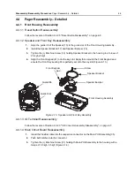
Figure 4-14. Main PCB Assembly
4.4.1.5 Switch PCB Assembly Reasassembly
1.
Insert the Flex into the respective connector on the Main PCB Assembly (35).
2.
Push both latches into the connector.
Figure 4-15. Assembling Switch PCB Assembly
3.
Apply the Screw fastener (3bond, TB1410B) around the thread of both Channel/ Volume
switches (Figure 4-16.).
4.
Tighten the Nut for Ch/Vol (24) holding the Channel/ Volume switches to the housing with
Crab Eye Nut Tool torque to 4.0 kgf~5.0 kgf
.
5.
Assemble the Volume Knob Kit (38, 39) and Channel Knob Kit (36, 37) (Figure 4-17.).
Screw
Main PCB Assembly
Latch
Flex
Connector
Switch PCB Assembly
Main PCB Assembly
Flex
Latch

