


Test Mode and Error Codes
4-1
4
Test Mode
and Error Codes
4
Front Panel Test Mode
The functions of the radio controls for the Front Panel Test Mode are as follows:
Test Mode/Entry
Test Mode allows radio checks to be performed in the field. To provide a level of
protection to the Test Mode entry, proceed according to the following sequence:
1.
Place radio in TRUNKING operation mode and wait for 6 seconds. (See
Quick Start card for instructions on how to enter that mode.)
2.
Turn radio off.
3.
Verify that RIB is off.
4.
Turn radio power supply (13.6 V DC) on .
5.
Turn radio on.
The radio enters Test Mode operation:
• Speaker unmutes.
• One beep is heard to indicate operation on the first test frequency
(default).
• Display shows "4 1" .
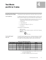
Test Mode/Channel
Selection
Use the PTT switch for channel selection. A short press and de-press on the PTT
switch (button-like push) will advance the radio to the next channel (cyclical) .
Seven channels are available during test mode, as shown in the table below.
(1). CC1-CC4 are control channels programmed in association with
the selected trunking system.
(2). M stands for modulation type (0-3). See Table 4-2.
Table 4-1 Test Mode/Channel Selection
Channel Number
Rx Frequency
Tx Frequency
Display
1
851.0125 MHz
806.0125 MHz
“M 1” (2)
2
869.9875 MHz
824.9875 MHz
“M 2” (2)
3
860.5125 MHz
815.5125 MHz
“M 3” (2)
4
CC1 (1)
CC1-45 MHz
“M 4” (2)
5
CC2 (1)
CC2-45 MHz
“M 5” (2)
6
CC3 (1)
CC3-45 MHz
“M 6” (2)
7
CC4 (1)
CC4-45 MHz
“M 7” (2)
MODE (4 IS INITIAL MODE)
CHANNEL


