Installation
2-3
NOTE
It is recommended to shorten the high
voltage cable as much as possible,
providing that the distance between the
antenna base and the ATU is short enough.
Use the appropriate ring lug, provided
separately in the kit, to reassemble the
shortened cable.
Step 1.
Attach the high voltage cable conductor to the
ATU RF output (see Figure
2-3). While holding the
high voltage cable, push the rubber yoke cover until it
slips on the yoke.
Figure 2-3. FKN4314A High Voltage Cable
Attachment
Step 2.
Attach the grounding braid of the high voltage
cable kit to the ATU ground terminal (see Figure
2-3).
Step 3.
Route the grounding braid between the ATU
mounting rails and the mounting surface. Align the
grounding braid eyelets with the holes in the mounting
rails and mount the ATU using the tapping screws
provided (see Figure
2-3).
Step 4.
If the grounding braid does not provide a good
ground to the vehicle's body, connect the supplied
grounding wire between the ATU ground terminal and
a good grounding point near the antenna base using the
supplied tapping screw and split washer.
Step 5.
Attach the other end of the high voltage cable
to the antenna base.
2.3.2.3 Cable
Interconnections
Step 1.
Route the RF cable between the ATU and the
radio.
Step 2.
Connect the RF coaxial cable to the ATU's RF
input.
Step 3.
Connect the RF cable to the radio.
Figure 2-4. ATU Electrical and Mechanical
Connections
Step 4.
Perform the operational check given in
paragraph 2.3.3.
2.3.3 OPERATIONAL
CHECK
When the system installation is completed, perform the
following operational check:
Step 1.
Install an in-line wattmeter between the radio
and the ATU.
Step 2.
Turn on the radio.
Step 3.
Key the radio and whistle into the microphone;
observe the forward and reverse power reading on the
wattmeter. The forward power should be at least three
times greater than the reverse power.
Step 4.
Perform step 3 for each channel used.
Summary of Contents for F2265A
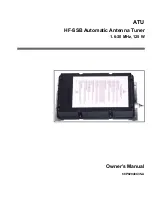
Page 1: ...ATU HF SSB Automatic Antenna Tuner 1 6 30 MHz 125 W Owner s Manual 68P02948C35 A ...
Page 2: ......
Page 3: ...ATU HF SSB Automatic Antenna Tuner 1 6 30 MHz 125 W Owner s Manual 68P02948C35 A ...
Page 4: ......
Page 10: ......
Page 12: ......


