Level 1 and 2 Service Manual
A1000
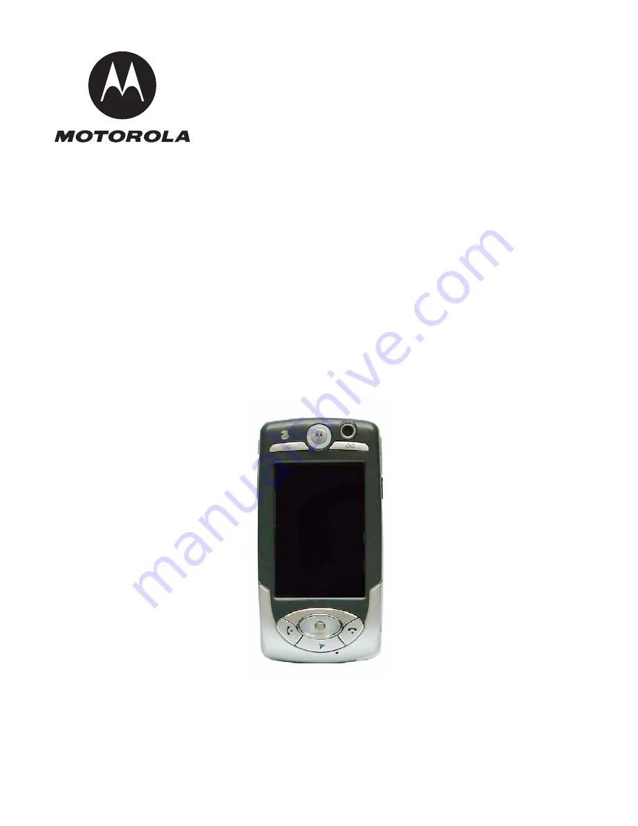
Wireless Telephone
GSM and WCDMA 900/1800/1900/2100 MHz
Page 1: ...Level 1 and 2 Service Manual A1000 Wireless Telephone A1000 GSM and WCDMA 900 1800 1900 2100 MHz ...
Page 2: ......
Page 3: ...ing the Battery 18 Removing and Replacing the USIM 20 Removing and Replacing the Rear Housing 21 Removing and Replacing the Transceiver Board 23 Removing and Replacing the Gaming Buttons 25 Removing and Replacing the Navigation Buttons 26 Removing and Replacing the Battery Shield 27 Removing and Replacing the Joystick Assembly 28 Removing and Replacing the Display Assembly 30 Removing and Replacin...
Page 4: ...ii October 4 2004 6809490A77 O Contents A1000 ...
Page 5: ...roduct Names Product names are listed on the front cover Product names are subject to change without notice Some product names as well as some frequency bands are available only in certain markets Product Changes When electrical mechanical or production changes are incorporated into Motorola products a revision letter is assigned to the chassis or kit affected for example A B or C and so on The ch...
Page 6: ...orola product and the Motorola computer programs with the Motorola product About This Service Manual Using this service manual and the suggestions contained in it assures proper installation operation and maintenance of A1000 telephones Refer questions about this manual to the nearest Customer Service Manager This manual contains mechanical service information required for the equipment described ...
Page 7: ...ginal phones will be repaired but not refurbished as standard Appointed Motorola Service Hubs will perform warranty and non warranty field service for level 2 assemblies and level 3 limited PCB component Motorola High Tech Centers will perform level 4 full component repairs Customer Support Customer support is available through dedicated Call Centers and in country help desks Product Service train...
Page 8: ...ber or other related major assembly along with a description of the related major assembly and of the component in question In the U S A to contact Motorola Inc on your TTY call 800 793 7834 Accessories and Aftermarket Division AAD Replacement parts test equipment and manuals can be ordered from AAD For EMEA spare parts call 49 461 803 1638 For Asia spare parts call 65 648 62995 U S A Outside U S ...
Page 9: ...quency Range UMTS TX 1920 to 1980 MHz Frequency MHz UARFCN1 5 where 9612 UARFCN1 9888 UARFCN1 in increments of 25 RX 2110 to 2170 MHz Frequency MHz UARFCN1 5 where 10562 UARFCN1 10838 UARFCN1 in increments of 25 Channel Spacing 200 kHz GSM DCS PCS 5MHz UMTS Channels 174 EGSM 374 DCS 274 PCS carriers with 8 ch Per carrier 11 UMTS Duplex Spacing 45 MHz GSM 95 MHz DCS 80 MHz PCS 190 MHz UMTS Modulati...
Page 10: ...n RPE LPC with LTP Bit Rate 13 0 kbps RF Power Output 32 dBm nominal GSM 28 5 dBm nominal DCS PCS Receive Sensitivity 102 dBm GSM 102 dBm DCS PCS RX Bit Error Rate 2 Table 3 UMTS System General Function Specification Speech Coding Type Adaptive Multirate AMR RF Power Output 21 dBm Error Vector Magnitude 13 9 Pout 20 dBm PN9 Bit Error Rate VER 0 1 12 2k 106 7 dBm ACLR 35 8 dB 5 MHz 43 dB 10 MHz ...
Page 11: ...hanced Multimedia Capability Audio Video Games MMS Unique 5 way Navigation Key Touchscreen based graphical user interface Full internet browser HTML xHTML WML XML Full Personal Information Manager PIM with Synchronization OTA Desktop Integrated Video Still Camera and Integrated A GPS Voice Recognition Driven Dialing and Menu Shortcuts Voice Note Voice Recorder 24 Polyphonic MIDI Ringer Sounds Prog...
Page 12: ...g shopping Receive information through alerts or display on map ahead of traffic congestion Receive roadside assistance with rescue service network and location information from the cellular network used to complement any information the pedestrian driver is able to provide ...
Page 13: ... The telephone s controls are located on the front and side of the phone as shown in Figure 1 Indicators in the form of icons are displayed on the LCD Figure 1 A1000 Controls Front and Right Side View Camera Earpiece Volume Keys Game A Key Game B Key Send Key 3 Key End Key Navigation Key Speakerphone Key Lock Key Camera Key 3 Key ...
Page 14: ...he display The status bar at the bottom of the display shows the current phone status Some of the phone functions must be performed from the home screen display see Figure 3 The term home screen display refers to the standard display you see when the phone is on and ready to use when you are not on a call or using the menu system Figure 2 Phone Controls Rear View Whether a phone displays all indic...
Page 15: ... The keyboard displays only when the cursor is in a text entry field Alert Mode Shows the currently selected alert mode Audio Vibrate Silent The alert mode indicates how the communicator notifies you of an incoming call or message To change the alert mode tap this indicator and select the setting you want 020850 o Figure 3 Home Screen Display Keyboard Launcher Bluetooth Phone Clock Alert Mode Loca...
Page 16: ...nt Location mode allows you to track your current location on the communicator screen Phone Shows the status of an active call Connected Muted displays when you have a new voice message and no active call Message Shows that you have a new message and what type Email SMS MMS If an MMS or SMS message sender s phone number is in your Contact list the indicator is white If the message sender s phone n...
Page 17: ...ns The communicator has many built in applications for communications personal organization and entertainment Every application has an associated icon Strong No signal High E D C B Empty Table 4 Status Light Indication Description Rapidly flashing green Incoming call phone number stored in Contacts Alternating green red Incoming call phone number not stored in Contacts Rapidly flashing amber Incom...
Page 18: ...s automatically saved The application icons see Table 5 open communicator applications Alert Settings Motorola wireless phones incorporate the VibraCall discreet vibrating alert that helps avoid disturbing others when a ringing phone is unacceptable You can set alerts to ring only vibrate only or no ring or vibrate An icon on the status bar displays the current alert mode setting Additionally the ...
Page 19: ...instructions refer to the appropriate user guide listed in the Related Publications section E Exercise care in handling any charged battery particularly when placing it inside a pocket purse or other container with metal objects All batteries can cause property damage and or bodily injury such as burns if a conductive material such as jewelry or keys contact exposed terminals The conductive materi...
Page 20: ...at and pointed ends Used to assemble disassemble phone 6680388B01 Tweezers plastic Used to assemble disassemble phone RSX4043 A Torque Driver Used to remove and replace screws Torque Driver Bit T 6 Plus Apex 440 6IP Torx Plus or equivalent Used to assemble disassemble phone HP34401A2 Digital Multimeter Used to measure battery voltage 1 To order in North America contact Motorola Aftermarket and Acc...
Page 21: ...p and away from the phone To Replace the Battery Door 1 Align the battery door tabs to the slots on the back of the phone 2 Lower the battery door onto the back of the phone 3 Slide the battery door into its final position G Many of the integrated devices used in this equipment are vulnerable to damage from electrostatic discharge ESD Ensure adequate static protection is in place when handling shi...
Page 22: ... Replace the Battery 1 If necessary remove the battery from its protective clear plastic case E Exercise care in handling any charged battery particularly when placing it inside a pocket purse or other container with metal objects All batteries can cause property damage and or bodily injury such as burns if a conductive material such as jewelry or keys contact exposed terminals The conductive mate...
Page 23: ...r 4 2004 19 Level 1 and 2 Service Manual Disassembly 2 Insert the battery top first under the tab at the top of the battery compart ment then press the top of the battery into place 3 Replace the battery door see page 17 ...
Page 24: ...sing it to static electricity water or dirt To Remove the USIM 1 Ensure the phone is off 2 Remove the battery door 3 Remove the battery 4 Slide the USIM card holder to unlock it and lift it to open 5 Slide the USIM out of the USIM card holder To Replace the USIM 1 To replace the USIM insert the USIM card in the card holder The card notch fits in the lower left corner and the gold contacts face dow...
Page 25: ...the battery door 3 Remove the battery 4 Remove the USIM 5 Using a driver with a T 6 Torx Plus bit remove the 8 screws that secure the rear housing to the front housing see Figure 7 G This product contains static sensitive devices Use anti static handling procedures to prevent electrostatic discharge ESD and component damage Figure 7 Removing the Rear Housing Screw Locations ...
Page 26: ...Housing 1 Align the rear housing to the front housing 2 Lower the rear housing onto the front housing Press it into place 3 Replace the 8 screws with a T 6 Torx Plus bit and torque them to 1 in lb 4 Replace the USIM battery and battery door as described in the procedures Figure 8 Removing the Rear Housing Continued 1 ...
Page 27: ... 4 Remove the USIM 5 Remove the rear housing 6 Remove the 2 T 6 screws with a T 6 Torx Plus bit at the top securing the transceiver board to the front housing 7 Partially lift the front housing off of the transceiver board G This product contains static sensitive devices Use anti static handling procedures to prevent electrostatic discharge ESD and component damage Figure 9 Removing the Transceive...
Page 28: ... Align the front housing over the transceiver board 2 Lower the front housing onto the transceiver board and press it into place 3 Replace the 2 T 6 screws with a T 6 Torx Plus bit and torque them to 1 in lb 4 Replace the rear housing USIM battery and battery door as described in the procedures Figure 10 Removing the Transceiver Board Front Housing 1 1 ...
Page 29: ...5 Remove the rear housing 6 Remove the transceiver board 7 Using plastic tweezers carefully lift the gaming button assembly from the front housing To replace the Gaming Buttons 1 Align the gaming button assembly over the front housing gaming button location and press into place 2 Replace the transceiver board rear housing USIM battery and battery door as described in the procedures Figure 11 Remov...
Page 30: ...ton assembly and lift it out of the front housing To Replace the Navigation Button Assembly 1 Align the navigation button assembly with the opening in the front housing and press into place 2 Ensure that the alignment holes on the button assembly fit over the alignment pins on the front housing there are a total of 6 alignment pins 3 Replace the transceiver board rear housing USIM battery and batt...
Page 31: ...ve the rear housing 6 Using tweezers release the locking tabs by separating the rear housing wall from the battery shield 7 Lift the battery shield out from the rear housing To Replace the Battery Shield 1 Align the transceiver board with the rear housing and press it in place 2 Replace the transceiver board rear housing USIM battery and battery door as described in the procedures Figure 13 Removi...
Page 32: ...ystick Assembly 1 Ensure the phone is off 2 Remove the battery door 3 Remove the battery 4 Remove the USIM 5 Remove the rear housing 6 Remove the transceiver board 7 Disengage the locking tabs on either side of the joystick assembly Figure 14 Removing and Replacing the Joystick Assembly Locking Tab Locking Tab ...
Page 33: ...Joystick Assembly 1 Align the joystick flex with its connector and press it into place 2 Align the 2 joystick locking tabs with the transceiver board and snap it into place 3 Replace the transceiver board rear housing USIM battery and battery door as described in the procedures Figure 15 Removing and Replacing the Joystick Assembly Joystick Flex Disassembly Tool ...
Page 34: ...ex from its connector 3 Release the display assembly clips from the transceiver on each side of the display assembly as shown in Figure 16 4 Carefully disengage the 2 display locking tabs 1 one each side of the display 5 Carefully lift the display assembly away from the transceiver board G The flexible printed cable connecting the display module to the display board is fragile Use extreme care whe...
Page 35: ...ard 2 Snap the 2 display locking tabs into place 3 Carefully press the display flex connector into the transceiver board display connector 4 Replace the joystick assembly transceiver board rear housing USIM battery and battery door as described in the procedures Figure 17 Removing the Display Assembly Display Assembly Display Locking Tab Transceiver Board ...
Page 36: ...ssembly 2 Disengage the 2 MFT assembly locking tabs 3 Lift the MFT assembly away from the transceiver board To Replace the MFT Assembly 1 Align the MFT assembly over the transceiver board and snap the locking tabs in place 2 Replace the display assembly joystick assembly transceiver board rear hous ing USIM battery and battery door as described in the procedures Figure 18 MFT Assembly Removal MFT ...
Page 37: ...nsceiver board Joystick Assembly Display Assembly MFT Assembly 2 Disengage the 2 camera gaming keypad locking tabs Note The rubber camera grommet covering the camera will easily fall out when the upper endo is removed 3 Using the disassembly tool carefully disengage the camera gaming keypad flex from its connector Figure 19 Camera Gaming Keypad Removal Camera Gaming Keypad Locking Tab Camera Gamin...
Page 38: ...ceiver board and press it into place 2 Align the camera gaming keypad with the transceiver board and snap the 2 locking tabs into place 3 Replace the MFT assembly display assembly joystick assembly transceiver board rear housing USIM battery and battery door as described in the procedures Figure 20 Disconnecting the Camera Gaming Flex Connector Camera Gaming Keypad Flex Connector Disassembly Tool ...
Page 39: ... disassembly tool carefully disengage the camera flex from its connector 3 Lift the camera away from the transceiver board To Replace the Camera 1 Align the camera flex with its connector on the transceiver board and press it into place 2 Replace the camera gaming keypad MFT assembly display assembly joystick assembly transceiver board rear housing USIM battery and battery door as described in the...
Page 40: ...ess to the network Identification Label Each Motorola GSM phone is labeled with a variety of identifying numbers The following section describes the current identifying labels Mechanical Serial Number MSN The MSN is an individual unit identity number and remains with the unit through out its life The MSN can be used to log and track a phone on Motorola s Service Center Database The MSN is divided ...
Page 41: ... is divided into the four sections shown in Figure 23 Other label number configurations are Transceiver Number Identifies the product type usually the SWF number e g V100 Package Number Identifies the equipment type mode and language pack in the phone 000808o Figure 23 IMEI Label Breakdown IMEI 16 Digits 6 Digits 2 Digits 6 Digits 2 Digits TAC FAC SNR IU Type Approval Code Distribution Center fact...
Page 42: ...ute a known good antenna If the fault is still present proceed to b b Transceiver board defective Replace transceiver board refer to 1c Verify that fault has been cleared and reassemble phone with new transceiver board 3 Display is erratic or provides partial or no display a Mating connections to or from transceiver board faulty Check general condition of flex and flex connector If flex and connec...
Page 43: ... defective SIM card If SIM card is not at fault proceed to b b Transceiver board defective Replace transceiver board refer to 1c Verify that fault has been cleared and reassemble phone with new transceiver board b Transceiver board defective Replace transceiver board refer to 1c Verify that fault has been cleared and reassemble phone with new transceiver board 9 Internal Charger not working Faulty...
Page 44: ...A1000 Part Numbers This section provides a reference for the parts associated with A1000 telephones Related Publications Motorola A1000 Wireless Phone User Guide English 68XXXXXX62 Motorola A1000 Wireless Phone Reference Guide English 68XXXXXX61 ...
Page 45: ... Front Endo Upper Assembly 3 SHN9738A Stylus 14 2690180N02 Elastomeric Shield 4 0387340Y01 Screws 8x 15 7289439N02 Display Assembly 5 1590089N01 Rear Housing Assembly 16 1590041N02 Front Housing Assembly 6 3887320Y01 Side Button 17 3889966N03 Navigation Keypad 7 0387340Y01 Screws 2x 18 3889967N01 Gaming Keypad 8 1589973N01 Rear Endo Upper Assembly 9 8488485N01 Transceiver Board 10 0189905N01 Camer...
Page 46: ...42 October 4 2004 6809490A77 O Part Numbers A1000 Exploded View Diagram Figure 24 Exploded View Diagram 1 2 3 4 5 7 6 8 9 11 12 10 13 14 15 16 18 17 ...
Page 47: ...the Ear SYN8908 Platform Stereo Headset CHYN4516 Universal Customizable One Touch standard monophonic headset SYN9351 SYN8419 Headset Retractable SYN9050 Bluetooth Headset HS801 Bluetooth Headset HS810 Bluetooth Headset HS820 CHYN4590 SYN9826 SYN0945 Bluetooth Speaker Phone SYN0736 Bluetooth PC USB Adaptor SYN0717 Self Install HF Retractable SYN0613 Universal Self Install Egret Style Base Unit Raz...
Page 48: ... clock 11 color display 10 conventions 3 copyrights computer software 2 D disassembly 17 display assembly removing and replacing 30 E email status bar indicator 12 emergency status bar indicator 12 status light 13 exploded view diagram 42 exploded view parts list 41 F FCC rules 1 flashing and flexing 39 G gaming buttons removing and replacing 25 GPRS 12 GPS 12 GSM 12 I icons applications 14 identi...
Page 49: ...gaming keypad 33 display assembly 30 gaming buttons 25 joystick assembly 28 MFT assembly 32 navigation buttons 26 rear housing 21 USIM 20 replacement parts contact information 4 replacing battery 18 battery door 17 battery shield 27 camera 35 display assembly 30 gaming buttons 25 joystick assembly 28 MFT assembly 32 navigation buttons 26 rear housing 21 USIM 20 ringing turning off 11 roaming statu...
Page 50: ... Level 1 and 2 Service Manual Index T test equipment 16 tools disassembly 16 U UMTS 12 USIM card installing 20 USIM removing and replacing 20 V vibrate mode indicator 11 turning on and off 11 voice message indicator 12 W warranty service 3 ...
Page 51: ......
Page 52: ...all other trademarks indicated as such herein are trademarks of Motorola Inc Reg U S Pat Tm Off 2004 Motorola Inc All rights reserved Personal Communications Sector 1500 Gateway Blvd Boynton Beach FL 33426 8292 6809490A77 6809490A77 O ...