background image


3-6 Managing 

Power 

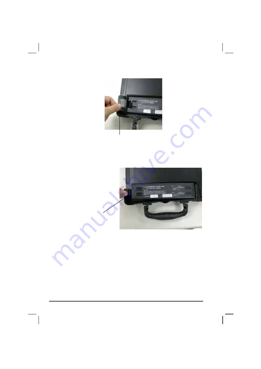
4.  Pull the battery pack. 


5.  Pull on the protruding strip to slide the battery pack to the left and lift 

the battery pack out of its compartment. 


6.  Insert the new battery into the compartment and slide the battery pack 

to the right to allow the proper connection of connectors. 

7.  In order to fixed battery pack, we put the battery pack block on the 

rear of the battery. 

8.  Replace the battery compartment cover and slide the battery cover 

latch outward to secure it. 

Battery Pack

Pull battery pack

Summary of Contents for 850

Page 1: ...Mobile Laptop 850 Model L3391B L3392B Motorola Inc Commercial Government and Industrial Solutions Sector All rights reserved Owner s Manual R03 Part No DDN7509 ...

Page 2: ...TRADEMARKS All brand and product names are trademarks or registered trademarks of their respective companies NOTE Information in this manual is subject to change without notice ...

Page 3: ...o communications However there is no guarantee that interference will not occur in a particular installation If this equipment does cause harmful interference to radio or television reception which can be determined by turning the equipment off and on the user is encouraged to try to correct the interference by one or more of the following measures Reorient or relocate the receiving antenna Increa...

Page 4: ...des Communications du Canada Products with the CE Marking comply with both the EMC directive 89 336 EEC and the Low Voltage Directive 73 23 EEC issued by the Commission of the European Community Compliance with these directives implies conformity to the following European Norms z EN50081 1 Electromagnetic compatibility Generic emmision standard z EN55022 conducted Emission Radiated Emission z EN61...

Page 5: ...location as failure to do so may cause the product to cause harm in accidents or other conditions Similarly Motorola strongly recommends that the unit not be situated for a prolonged period in an position that places the antennas directly against the human body for example by tucking an operational radio equipped unit under one s arm NOTE The radio modems in the ML850 may continue to transmit and ...

Page 6: ...ritype eller en tilsvarende type anbefalt av apparatfabrikanten Brukte batterier kasseres i henhold til fabrikantens instruksjoner SWEDISH VARNING Explosionsfara vid felaktigt batteribyte Använd samma batterityp eller en ekvivalent typ som rekommenderas av apparattillverkaren Kassera använt batteri enligt fabrikantens instruktion FINNISH VAROITUS Paristo voi räjähtää jos se on virheellisesti asenn...

Page 7: ...ded by the equipment manufacturer Discard used batteries according to manufacturer s instructions DEUTSCH VORSICHT Explosionsgefahr bei unsachgemäßem Austausch der Batterie Ersatz nur durch denselben oder einen vom Hersteller empfohlenen gleich wertigen Typ Entsorgung gebrauchter Batterien nach Angaben des Herstellers ...

Page 8: ...unicipal waste stream Check with your local solid waste officials for details in your area for recycling options or proper disposal About the Modem Caution 1 Never install telephone wiring during a lightning storm 2 Never install telephone jacks in wet locations unless the jack is specifically designed for wet locations 3 Never touch uninsulated telephone wires or terminals unless the telephone li...

Page 9: ...xible cord One end terminates with a Tandem blade grounding listed molded on attachments plug with a 6 A 250 V NEMA 6 15P configuration other end terminates with a molded on appliance coupler FCC RF Radiation Exposure Statement This equipment complies with FCC RF radiation exposure limits set forth for an uncontrolled environment This equipment should be installed and operated with a Minimum dista...

Page 10: ...Running 1 2 Unpacking 1 2 Connecting to AC Power 1 2 Opening the Cover 1 3 Closing the Cover 1 4 Turning On and Off the Computer 1 4 Taking a Look at the Computer 1 5 Right side Components 1 5 Left side Components 1 7 Rear Components 1 8 Front Components 1 9 Top open Components 1 11 ...

Page 11: ...Key 2 6 Hot keys 2 6 Using the Touchpad 2 8 Configuring the Touchpad 2 9 Using the Touchscreen optional 2 10 Configuring the Touchscreen 2 11 Using the Floppy Disk Drive optional 2 12 Inserting and Ejecting Floppy Disks 2 12 Using the Hard Disk Drive 2 14 Using the CD DVD COMBO Drive optional 2 15 Inserting and Removing a CD 2 16 Using the Video Features 2 17 Configuring the Display Modes 2 17 Usi...

Page 12: ...tery Pack 3 3 Initializing the Battery Pack 3 4 Checking the Battery Level 3 4 Replacing the Battery Pack 3 4 Battery Low Signals and Actions 3 7 Power Management 3 8 Suspend to Disk Suspend mode 3 8 Power Saving Tips 3 10 Chapter 4 Expanding Your Computer 4 1 Connecting an External Monitor optional 4 2 Connecting a Parallel Device optional 4 3 Connecting a Serial Device 4 4 Connecting a USB Devic...

Page 13: ...g Around and Making Selections 5 4 Main Menu 5 5 Date and Time 5 5 Intelnal and Numlock 5 6 USB Emulation 5 6 Advanced Menu 5 7 Geyserville Support 5 7 Shared video Memory 5 8 Com Ports 5 8 HDD Heater 5 9 Security Menu 5 10 Power on Password 5 10 Set Password 5 11 Boot Menu 5 12 Boot Sequence 5 12 Exit Menu 5 13 Save Change and Exit 5 13 Discard Change and Exit 5 13 Get Default Values 5 13 ...

Page 14: ... Installing Touch Screen Driver for Windows XP 6 8 Touchscreen Utility 6 18 Chapter 7 Caring for the Computer 7 1 Protecting the Computer 7 2 Using the Password 7 2 Using an Anti Virus Strategy 7 2 Taking Care of the Computer 7 3 Location Guidelines 7 3 General Guidelines 7 3 Cleaning Guidelines 7 4 Battery Pack Guidelines 7 4 When Traveling 7 5 Chapter 8 Troubleshooting 8 1 Preliminary Checklist ...

Page 15: ... Problems 8 11 Power Management Problems for Windows 8 11 Printer Problems connected through optional docking station 8 12 Software Problems 8 13 Sound Problems 8 13 Startup Problems 8 14 Other Problems 8 14 Resetting the Computer 8 15 Appendix A Specifications A 1 Preface This manual contains information that will help you operate the computer It is divided into 8 chapters and an appendix Chapter...

Page 16: ...CU Setup Configuration Utility describes the SCU program that configures the computer s BIOS settings Chapter 6 Installing Software Drivers describes how to install the drivers and utilities supplied with the computer Chapter 7 Caring for the Computer gives you tips in care and maintenance Chapter 8 Troubleshooting gives solutions to common problems you may encounter when using the computer Append...

Page 17: ...d keys are shown in a bold typeset For example Press Enter to complete When keys are joined by a plus sign press the first key and while keeping the first key down press the remaining keys finally release all the keys When necessary keys are also shown in graphics A title command setup item or button that you can see on the screen is shown in boldface A value or an option that you can select for a...

Page 18: ... reproduced in any manner without the express written permission of Motorola Furthermore the purchase of Motorola products shall not be deemed to grant either directly or by implication estoppel or otherwise any license under the copyrights patents or patent applications of Motorola except for the normal non exclusive royalty free license to use that arises by operation of law in the sale of a pro...

Page 19: ...otorola according to the terms of this warranty Repaired or replaced Product is warranted for the balance of the original applicable warranty period All replaced parts of the Product shall become the property of Motorola This express limited warranty is extended by Motorola to the original end user purchaser purchasing the Product for purposes of leasing or for commercial industrial or governmenta...

Page 20: ...lusive is the exclusive remedy THIS WARRANTY IS GIVEN IN LIEU OF ALL OTHER EXPRESS WARRANTIES MOTOROLA DISCLAIMS ALL OTHER WARRANTIES OR CONDITIONS EXPRESS OR IMPLIED INCLUDING THE IMPLIED WARRANTIES OR CONDITIONS OF MERCHANTABILITY AND FITNESS FOR A PARTICULAR PURPOSE IN NO EVENT SHALL MOTOROLA BE LIABLE FOR DAMAGES IN EXCESS OF THE PURCHASE OF PRICE THE PRODUCT FOR ANY LOSS OF USE LOSS OF TIME I...

Page 21: ...y warranty claim F Product which has had the serial number removed or made illegible G Accessories including batteries carry their own separate limited One 1 year warranty H Freight costs to the repair depot I A Product which due to illegal or unauthorized alteration of the software firmware in the Product does not function in accordance with Motorola s published specifications or with the FCC typ...

Page 22: ...ing A That Motorola will be notified promptly in writing by such purchaser of any notice of such claim B That Motorola will have sole control of the defense of such suit and all negotiations for its settlement or compromise and C Should the Product or its parts become or in Motorola s opinion be likely to become the subject of a claim of infringement of a United States patent that such purchaser w...

Page 23: ...s the exclusive rights to reproduce in copies and distribute copies of such Motorola software Motorola software may be used only in the Product in which the software was originally embodied and such software in such Product may not be replaced copied distributed modified in any way or used to produce any derivative thereof No other use including without limitation alteration modification reproduct...

Page 24: ...ronment This equipment generates uses and can radiate radio frequency energy and if not installed and used in accordance with the instruction manual may cause harmful interference to radio communications Trademarks Motorola and the Motorola logo are registered trademarks of Motorola Inc Mobile Laptop 850 are trademarks of Motorola Microsoft MS DOS MS Windows and Windows are registered trademarks o...

Page 25: ...tion to extend the capabilities of input output devices This chapter first tells you step by step how to get the computer up and running You will find instructions for these procedures z Unpacking z Connecting to AC power z Opening the cover z Connecting the computer to the docking station z Turning on the computer z Turning off the computer Then you will find a section briefly introducing the ext...

Page 26: ...DC Optional External battery charger Optional This Operation Manual Touchscreen Pen Optional 3M High Performance Colth Inspect all the items If any item is damaged or missing notify your dealer immediately Keep the shipping carton and packing materials in case you need to ship or store the computer in the future Connecting to AC Power The computer operates either on the external AC power or intern...

Page 27: ...mputer CAUTION When you disconnect the AC adapter disconnect from the electrical outlet first and then from the computer docking station A reverse procedure may damage the AC adapter or the computer docking station When unplugging the connector always hold the plug head Never pull on the cord NOTE When the AC adapter is connected it also charges the battery pack For information on using battery po...

Page 28: ...port To prevent the computer from accidentally waking up from Suspend mode during transport without the user s knowledge Turning On and Off the Computer Turning On 1 Make sure the computer docking station is connected to AC power 2 Press the power button 3 Each time the computer is turned on it performs a Power On Self test POST and the operating system such as Windows should start Power ...

Page 29: ...n CAUTION If you have to turn the computer on again immediately after turning it off wait for at least five seconds Turning the computer off and on rapidly can damage it Taking a Look at the Computer This section identifies the external components of the computer and briefly describes the function of each component Right Side Components Ref Component See Also Device Indicators Shows the current st...

Page 30: ...d and powered on System State Indicator glows green when the computer is powered on Glows orange when the computer is in Suspend mode AC Power Indicator glows green when computer is connected to AC power and is powered on PC Card Slot Accepts a PC Card for additional functions RJ 45 Connector Connects the LAN cable RJ 11 Connector Connects the telephone line USB Port Connects an USB device such as...

Page 31: ...ing Started 1 7 Left Side Components Ref Component Description See Also Audio Output Connector Connects a hi fi set radio set synthesizer walkman etc Microphone In Connector Connects an external microphone ...

Page 32: ...on See Also USB Port Each of the two ports connects a USB device such as a USB floppy drive printer digital camera joystick and more VGA Port Connects an external monitor Serial Port Connects a serial device such as mouse Power Connector Connects the AC adapter ...

Page 33: ...ing station Wireless Modem or GSM Antenna Serves as the antenna for the optional wireless modem or GSM Touchscreen Pen Provides a convenient way to use the touchscreen Can be stretched for better grip and handing Top Cover Latch Locks the top cover Wireless LAN Antenna Serves as the antenna for the WLAN It is built in the handle ...

Page 34: ... Speaker Sends out sound and voice from the computer Battery Compartment Cover Open the cover to access the battery pack Battery Cover Latch Locks the battery compartment Docking Connector Serves as the interface between the docking station and the computer ...

Page 35: ...dicators Shows the current status of the computer s devices Caps Lock Indicator glows green when Caps Lock key is pressed and its function is activated Num Lock Indicator glows green when Num Lk key is pressed and its function is activated Scroll Lock Indicator glows green when Scroll Lk key is pressed and its function is activated ...

Page 36: ...er ON and OFF Where to Go from Here As your computer is ready for operation you may want to do any of the following now For this purpose Do this To know more about the computer Go on to the next chapter To install the operating system if your dealer has not already done so See the operating system manual To know more about the operating system Read the operating system manual To install the driver...

Page 37: ...ut are new to notebook computers you may choose to read only the parts containing information unique to your computer Described in this chapter are the operating basics of these components Keyboard Touchpad Touchscreen Floppy disk drive when connected to docking station Hard disk drive CD DVD drive when connected to docking station And these features Starting and stopping the computer Function key...

Page 38: ...rams to run on The most widely used operating system today is Microsoft Windows Stopping the Computer When you finish a working session you can stop the computer by turning off power or leaving the computer in Standby or Suspend mode To stop in this mode Do this To start up or resume again Off Follow the shutdown procedure of your operating system This can prevent loss of unsaved data or damage to...

Page 39: ...s in Windows you can place the computer in Suspend mode by pressing the power button or by closing the display cover Press the power button If you choose to stop in Standby or Suspend mode you can return to where you left off the next time you start up the computer See Power Management in Chapter 3 for more information ...

Page 40: ...sed in combination with other keys for program specific functions The Alternate key is normally used in combination with other keys for program specific functions The Escape key is usually used for stopping a process Examples are exiting a program and canceling a command The function depends on the program you are using When the lock keys Caps Lock Num Lk and Scroll Lk are pressed their correspond...

Page 41: ... keypad area you can turn Num Lk off or you can press Fn and then the letter without turning Num Lk off Some software may not be able to use the numeric keypad on the computer If so use the numeric keypad on an external keyboard instead Euro Symbol If your Windows supports the Euro dollar sign you can press the sign on the keyboard To press the Euro sign on the keyboard hold down either of the Alt...

Page 42: ...d by the color of blue on the keycap To perform a desired function first press and hold Fn then press the other key Hot Keys Hot keys refer to a combination of keys that can be pressed any time to activate special functions of the computer Most hot keys operate in a cyclic way Each time a hot key combination is pressed it shifts the corresponding function to the other or next choice You can easily...

Page 43: ...or is connected through the docking station LCD CRT monitor Display on both NOTE If the display mode is set to 256 colors or lower or in DOS mode there will be only two modes for selecting CRT only and Display on both Fn F10 Serves as the sleep button that you can define with Windows Power Management See Power Management in chapter 3 ...

Page 44: ...o buttons To use the touchpad place your forefinger or thumb on the pad The rectangular pad acts like a miniature duplicate of your display As you slide your fingertip across the pad the pointer also called cursor on the screen moves accordingly When your finger reaches the edge of the pad simply relocate yourself by lifting the finger and placing it on the other side of the pad Here are some comm...

Page 45: ...e your finger on the bottom edge of the pad and slide your finger left and right This function works only after you install the touchpad driver supplied with the computer and it may not work for all applications TABLE NOTE If you swap the left and right buttons tapping on the touchpad as an alternative method of pressing the left button will no longer be valid Configuring the Touchpad You may want...

Page 46: ...handle of the computer refer to Rear Components on chapter 1 To use the touchscreen place the touchscreen pen or your forefinger on the touchscreen As you slide your pen or fingertip across the screen the pointer or cursor on the screen moves in the same direction across the screen as your fingertip or pen moves across the screen Here are some common terms that you should know when using the touch...

Page 47: ...th the computer and it may not work for all applications TABLE NOTE If you swap the left and right buttons tapping on the touchscreen as an alternative method of pressing the left mouse button will no longer be valid Configuring the Touchscreen You may want to configure the touchscreen to suit your needs You can also change the size of the on screen pointer the speed of the pointer and so on To co...

Page 48: ...o you can transfer information from one computer to another The floppy disk drive is a high density 3 5 inch one which can read and write to either double density 2DD 720 KB floppy disks or high density 2HD 1 44 MB floppy disks Notice that both types of floppy disk have an arrow imprinted on the front upper left corner and a sliding write protect tab on the bottom left corner as illustrated above ...

Page 49: ...ator is off and then press the eject button on the drive When the floppy disk pops out of the drive remove the floppy disk and store it properly CAUTION Never turn off or reset the computer while the floppy disk drive in use indicator is on Always store your floppy disks in a safe clean container to protect them from the environment and magnetic fields A floppy disk must be formatted before you ca...

Page 50: ...the latest in fast reliable mass storage by integrating all the control circuitry necessary for operation directly onto the drive itself This allows the drive manufacturer to carefully optimize drive performance CAUTION Make regular backups of your data files from your hard disk drive to floppy disks or other storage media Never try to remove or install the hard disk drive while the computer is po...

Page 51: ...but also writes to CD R and CD RW discs A DVD ROM drive can read DVD Digital Versatile Disc discs in addition to the above discs CAUTION 1 When inserting a CD do not use force 2 Make sure the CD is correctly inserted into the tray and then close the tray 3 Do not leave the CD tray open Also avoid touching the lens in the tray with your hand If the lens becomes dirty the CD ROM may malfunction 4 Do...

Page 52: ...ended 3 To insert a CD put down the CD in the tray with its label facing up Slightly press the center of the CD until it clicks into place To remove a CD hold the CD by its outer edge and lift it up from the tray 4 Gently push the tray back into the drive NOTE In the unlikely event that you are unable to release the CD tray by pressing the eject button you can manually release the CD See CD DVD Dr...

Page 53: ... is closed If you want to use the computer with the LCD closed set None to the When I close the lid of my portable computer option in the Power Management properties Thus the computer does not enter Standby or Suspend mode when the LCD is closed Configuring the Display Modes NOTE To take advantage of the enhanced video capabilities the video driver supplied with your computer must be installed You...

Page 54: ...puter 2 18 Display Mode LCD Only CRT Only Simultaneous Display Resolution Colors 8 bit 16 bit 24 bit 640x480 32 bit 8 bit 16 bit 24 bit 720x480 32 bit 8 bit 16 bit 24 bit 800x600 32 bit 8 bit 16 bit 24 bit 848x480 32 bit ...

Page 55: ...Simultaneous Display 8 bit 16 bit 24 bit 1024x768 32 bit 8 bit 16 bit 24 bit 1152x864 32 bit 8 bit 16 bit 1280x1024 24 bit 8 bit 1600x1200 16 bit TABLE NOTE 8 bit 256 colors 16 bit High Color or 65 536 64 K colors 24 and 32 bit True Color 16 770 000 16 M colors ...

Page 56: ...ter and the optional docking station External audio connectors located on the left side of the computer or on the right side of the optional docking station Ways of playing and recording sound vary with the operating system used See your operating system documentation or online help for specific information Connecting Audio Devices For higher audio quality you can send or receive sound through ext...

Page 57: ...to the modem connect the end nearest the core on the modem cable to the computer s RJ 11 connector and the other end to the telephone line Using the LAN NOTE for Windows 2000 To take advantage of the LAN feature the LAN driver supplied with your computer must be installed The internal 100Base T LAN Local Area Network module allows you to connect your computer to a network It supports data transfer...

Page 58: ...dealer instead of the computer manufacturer contact your dealer for the correct driver to use Configuring the WLAN After driver installation you can use the WLAN utility to configure and monitor your WLAN connection If you are using Windows XP you can also use its built in WLAN utility Follow this procedure to launch the WLAN utility in Windows XP 1 Select Control Panel from the Start menu 2 Click...

Page 59: ...al battery performance it is important that you use the battery in the proper way The topics in this chapter include What is an AC adapter How to charge the battery pack When and how to initialize the battery pack How to check the battery level How to replace the battery pack What happens when the battery is low and what actions to take What is Power Management How to save power ...

Page 60: ... When unplugging the connector always hold the plug head Never pull on the cord The AC adapter serves as a converter from AC Alternating Current to DC Direct Current power because your computer runs on DC power but an electrical outlet usually provides AC power It also charges the battery pack when connected to AC power The AC adapter operates on any voltage in the range of 100 240 V AC The car ad...

Page 61: ... Battery Pack This computer is allowed to work in high temperature But in order to prevent the degradation of the battery charging circuitry might stop charging before fully charged Recommend recharge the battery pack in an environment temperature range of 10 C to 30 C The recharging time varies based on the usage conditions Recharging takes longer than usual when temperature is below 10 C The low...

Page 62: ...may automatically lessen due to the self discharge process 0 21 per day even when the battery pack is fully charged 100 This happens no matter if the battery pack is installed in the computer Initializing the Battery Pack The battery pack is not charged when the computer is first bought Make sure to charge it at least 8 hours before use it for the first time Charging automatically starts when the ...

Page 63: ...not rub eyes and immediately flush eyes with clear water and see a doctor as soon as possible If you often rely on battery power for a long period of time while traveling you may consider the purchase of an additional battery pack from your dealer and keep it with you in a fully charged state as a backup To replace the battery pack follow these steps 1 Make sure the computer is not turned on or co...

Page 64: ...artment 6 Insert the new battery into the compartment and slide the battery pack to the right to allow the proper connection of connectors 7 In order to fixed battery pack we put the battery pack block on the rear of the battery 8 Replace the battery compartment cover and slide the battery cover latch outward to secure it Battery Pack Pull battery pack ...

Page 65: ...u are using the audio subsystem PC card hard or CD ROM or floppy disk drives the battery might run out of charge very quickly Always respond to Battery Low by placing your computer on suspend to disk if enabled under O S program and turn off or system will continue on until battery is dead CAUTION If you are using a flash PC card do not access the card during battery low periods This is because th...

Page 66: ...riod Power to the display is turned off When the display has been idle for a set period When the entire system has been idle for a set period When you press Fn F10 When you close the cover The computer enters Standby mode The hard disk and display are turned off and the entire system consumes less power When you press the power button When you press the power button When you press Fn F10 The compu...

Page 67: ...mode Suspend to disk is a very useful feature People frequently open many applications when they use computers It takes some time to get all these applications open and running and normally they all have to be closed before the system can be turned off When you use the Suspend to disk feature you do not have to close the applications The computer stores the state of your computer to a file on the ...

Page 68: ...ected to these ports See Components Menu in Chapter 5 If you work with an application that uses the serial port exit the application when you finish using it If you have a PC Card installed remove it when not in use Some PC Cards drain power even while they are inactive Turn off the computer when you are not using it We recommend that you keep the AC adaptor with the computer whenever possible eve...

Page 69: ...g other peripheral devices When using a device be sure to read the instructions accompanying the device together with the relevant section in this chapter This chapter gives guidelines on installing and using these devices External monitor Parallel device through the optional docking station Serial device USB device PC Card ...

Page 70: ...other end to an electrical outlet 4 To use the monitor turn on the monitor before turning on the computer 5 The monitor should respond by default If not you can switch the display to the monitor or to both simultaneous displays by pressing Fn F9 In Windows you can also change the display through the settings in Display Properties 6 You can change display settings through your operating system See ...

Page 71: ...tional peripheral port Follow this procedure to connect a parallel device 1 Make sure that the LPT Port item is set properly in the BIOS Setup program See Advanced Menu in Chapter 5 for information 2 Make sure the computer is not turned on 3 Plug the parallel device s cable to the docking station s parallel port 4 If the parallel device has independent power plug its power cord into an electrical ...

Page 72: ...information 2 Make sure the computer is not turned on 3 Plug the device cable to the serial port on the computer NOTE When the computer is connected to the optional docking station plug its cable to the serial port on the rear of the docking station instead of using the serial port of the computer 4 Turn on the computer NOTE Portable modems that derive power through the serial port cannot be used ...

Page 73: ...ou can install and remove USB devices without turning off the computer With its multiple connection capability up to 127 devices can be connected in a daisy chain configuration In addition you can use a USB hub that converts a single USB connector into multiple ports where USB devices can be connected To connect a standard USB device simply plug the device cable to the USB port on the computer NOT...

Page 74: ...ing a PC Card NOTES Some PC Cards require additional system resources Before using such PC card you may have to free other system resources for the PC Card Although some PC Cards can be inserted and removed without turning off the computer you cannot remove or install PC Cards during Standby mode To insert a PC Card 1 Locate the PC Card slot on the right side of the computer 2 Slide the PC Card wi...

Page 75: ...lick the PC Card icon in Control Panel to stop the card 2 Push the eject button and the card will slide out slightly 3 Pull the card out of the slot System Memory Upgrade You can upgrade your computer by changing system memory to a maximum of 1GB on the DDR SDRAM slot However to avoid damage during the installation procedure please ask your dealer for help ...

Page 76: ...Expanding Your Computer 4 8 ...

Page 77: ...s of the computer BIOS are a layer of software called firmware that translates instructions from other layers of software into instructions that the computer hardware can understand The BIOS settings are needed by your computer to identify the types of installed devices and establish special features This chapter tells you how to use the SCU program ...

Page 78: ...mize system performance Starting SCU NOTES The Setup screens shown in this chapter are for your reference only The actual items or settings on your computer may differ The Setup program may have been updated after the publication of this manual The settings you select in your operating system might override similar settings in Setup To run SCU press F2 when the prompt appears in the left corner of...

Page 79: ...itles of the available menus Each menu title brings a specific menu The center left column of the menu contains items that you can set for the selected menu title The right column of the menu provides help information of the selected item The bottom lines give keyboard instructions for moving around and making selections ...

Page 80: ...n an item is selected Space bar Cycles through the pre defined value for the selected item Pressing the space bar brings up the next value pressing the minus key does the contrary Key Function Esc 1 Exits the SCU program 2 Returns to the previous menu if in a submenu 3 Closes the options window if one is open NOTE You are advised to use the touchpad or mouse if installed as it is more straightforw...

Page 81: ...Setup Configuration Utility 5 5 Main Menu The Main menu contains the basic configuration settings of the system Date and Time Sets the system date and time ...

Page 82: ...enabled you can press and hold FN and then press a letter key to enter a number even if Num Lock is turned off When this is disabled you cannot enter a number with the above method A check mark indicates enabled while undline _ indicates disabled USB Emulation enables or disables the system s support for the USB port in DOS mode ...

Page 83: ...of the CPU The Geyserville feature helps conserve battery life by decreasing the CPU s running speed under certain conditions while still maintaining a high performance If this item is enabled the CPU will automatically change its speed whenever necessary based on the Power Scheme setting in Windows s Control Panel If this item is disabled the CPU will always run in the lowest speed 600 MHz ...

Page 84: ...Setup Configuration Utility 5 8 Shared Video Memory sets the shared memory size of the video controller The options are 4M 8M 16M and 32M Com Ports ...

Page 85: ...first stage increases HDD temperature 0 7 C per minute User can enable disable heating function in SCU If heating function is enabled and the ambient temperature is below threshold of activating heater HDD heater will start to work function When user press power button under low temperature below 2 C CHG_GED and FULL_LED will flash together indicating automatic power on press has been started When...

Page 86: ...Password Set Password allows you to set the password for your system When typing password first make sure that Num Lock is off then type your password in the entry fields and press Enter Confirm your password by typing it again and pressing Enter If the Enable Password to Power on sub item is enabled the set password is always required to boot the computer ...

Page 87: ...g Enter If the Enable Password to SCU sub item is enabled the set password is always required to enter SCU Hard Disk Boot Sector sets if a warning message will appear when the hard disk boot sector partition table has been changed A check mark indicates enabled while an underline _ indicates disabled The default setting is disabled CAUTION sets this item to disabled before installing an operating ...

Page 88: ...e first device but if it is not available will try the next boot device If you set the first boot device to LAN Boot the system will boot from the LAN server first The options are Hard Disk Drive CD ROM Drive Floppy Disk Drive and LAN Boot The default setting is Floppy Disk Drive Hard Disk Drive CD ROM Drive then LAN Boot Note If you set all booting options to the same device then the computer wil...

Page 89: ...must save and exit so that the new setting can take effect Save Change and Exit saves the changes you have made and exits SCU Discard Changes and Exit exits SCU without saving the changes you have made Get Default Values loads factory default values for all the items Load Previous Values loads CMOS values before running SCU ...

Page 90: ...Setup Configuration Utility 5 14 ...

Page 91: ...uter some operating systems require custom software known as drivers to be installed If you purchased the computer with Windows pre installed your dealer may have already installed the drivers If not you need to install the drivers using the CD supplied with your computer This chapter describes how to install the drivers ...

Page 92: ...ndows 2000 and Windows XP only The available items may differ according to your computer model and Operating System An autorun is provided on the driver CD to help you easily install the drivers As you insert the driver CD the autorun program automatically starts If you need to start the program manually run the Autorun exe program from the Setup directory of the driver CD Note If driver CD versio...

Page 93: ...from to the Motorola ML850 Motorola recommends using Symantec Ghost tm Multi Cast server via Ethernet This functionality is provided in the Symantec Ghost tm Corporate Edition Please contact Symantec for more information b Install only To install an image onto the ML850 HDD via CDROM Motorola recommends the use of the ML850 Desk Dock The ML850 Desk Dock includes a 3 5 floppy and a CDROM drive Moto...

Page 94: ...tall the necessary driver just click on the particular option and follow the onscreen instructions to continue and complete installation Device Driver Press the Device driver button the system will auto install include VGA Audio Modem LAN Wireless LAN USB 2 0 DirectX 8 1 Chipset driver etc ...

Page 95: ... Window 2000 LAN Wireless LAN Allows you to use the network function of the computer USB 2 0 Allows your system to connect to USB 2 0 devices DirectX 8 1 Allows you to take full advantage of the multimedia applications Chipset Ensures the full function of the following drivers Install this main chipset driver installing the device drivers Touchscreen Allows you to use your fingers as a pointing de...

Page 96: ...em The driver should now be loaded 4 After the system has finished rebooting click on the PenMount Monitor icon located on the taskbar to bring up the PenMount Control Panel 5 Select the Standard Calibrate folder and click on OK button 6 If you need 4 9 16 25 dot of the calibrate we suggest select Advanced Calibrate button to calibrate 7 Click on the four sides points and the plus sign on the scre...

Page 97: ...Installing Software Drivers 6 7 Installing Drivers for Windows XP To set up the necessary drivers for Windows XP click on TOUCH SCREEN on the initial screen The following screen appears ...

Page 98: ...6 8 Install Touch Screen Driver for Windows XP Hardware Install 1 Insert the driver CD to the CD drive to bring up the following screen Select WINXP Click on TouchScreen to continue and follow the on screen instruction to continue ...

Page 99: ...Installing Software Drivers 6 9 2 When the TSRC XP htm file appear then select START Control Panel button ...

Page 100: ...Installing Software Drivers 6 10 3 When the Control Panel screen appear then click on performance and Maintenance button ...

Page 101: ...Installing Software Drivers 6 11 4 When the Performance and Maintenance screen appear and then click on System button ...

Page 102: ...Installing Software Drivers 6 12 5 When the System Properties screen appear and then click on Hardware and Device Manager button ...

Page 103: ...Installing Software Drivers 6 13 6 When the Device Manager screen appear then click on Unknown device and then click on the Properties icon ...

Page 104: ...Installing Software Drivers 6 14 7 When the Unknown Device Properties screen appear and then click on Reinstall Driver button ...

Page 105: ...g Software Drivers 6 15 8 When the Hardware Update Wizard appears click on Install the software automatically Recommand then click on Next 9 When the Hardware Installation screen appears click on Continue Anyway ...

Page 106: ...Installing Software Drivers 6 16 10 When the Hardware Update Wizard screen appears click on Finish button ...

Page 107: ...Installing Software Drivers 6 17 11 When the PenMount DMC9000 and DMC9100 Properties screen appears click on Close button to exit the driver installation ...

Page 108: ...talling Software Drivers 6 18 Touchscreen Utility To install the touchscreen utility perform the following 1 Insert the driver CD to the CD drive to bring up the following screen 2 Click on Start then Run ...

Page 109: ...etup 5 When the InstallShield Wizard appears click on Next to continue 6 Select I accept the terms in the license agreement then click on Next 7 When the Ready to Install the Program screen appears clcik on Install to continue 8 Reboot the system 9 After the system has restarted click on the PM icon located on the lower right portion of your taskbar to bring up the PENMOUNT Control Panel ...

Page 110: ... the Calibrate folder and click on the Calibrate button 11 If you need 4 9 16 25 dot of the calibrate we suggest select Advanced Calibrate button to calibrate 12 Click on the four sides red points and plus sign on the screen to calibrate your PENMOUNT pen to start using your ML 850 s Touchscreen ...

Page 111: ...and reduce the risk of damage to your computer This chapter gives you guidelines covering these areas of maintenance How to protect the computer What to note when using and storing the computer How to clean the computer What to note when using the battery pack What to note when traveling with the computer ...

Page 112: ...ears on the screen whenever the computer is turned on The password is set via the SCU program See Startup Menu in Chapter 5 for instructions Using an Anti Virus Strategy New viruses are always being developed nowadays and they are attacking computers even more easily with emails so commonly used worldwide The Security feature of the SCU program protects the boot sector of the hard disk To enable t...

Page 113: ...can generate a strong magnetic field such as a TV refrigerator motor or a large audio speaker Do not move the computer abruptly from a cold to a warm place A temperature difference of more than 10 C 18 F will cause condensation inside the unit which may damage the storage media Do not place the computer on an unsteady surface General Guidelines Do not place heavy objects on top of the computer as ...

Page 114: ... avoid extreme heat cold and direct sunlight Do not use with any other computer Do not put into a microwave Do not expose the battery pack to water or allow it become wet Do not place battery pack together with articles such as necklaces or hairpins when carrying or storing Recharge the battery pack when it is nearly discharged When recharging make sure the battery pack is fully charged Doing so m...

Page 115: ...page 3 5 When Traveling Before traveling with your computer make a backup of your hard disk data into floppy disks or other storage devices As an added precaution bring along an extra copy of your important data Make sure the battery pack is fully charged Make sure the computer is turned off Do not leave objects that will press onto the display Disconnect the AC adapter from the computer and take ...

Page 116: ...7 6 Caring for the Computer If you plan to travel abroad with your computer consult your dealer for the appropriate AC power cord for use in your country of destination ...

Page 117: ...uter problems When you encounter any problem it might be a typical problem that can easily be solved This chapter tells you what actions to take when solving common computer problems It is divided into three sections Preliminary checklist Solving common problems Resetting the computer ...

Page 118: ... sure that the cable connections are correct and secure Make sure that the configuration information is properly set in the SCU program Make sure that all the device drivers are correctly installed Make notes of your observations Are there any messages on the screen Do any indicators light Do you hear any beeps Detailed descriptions are useful to the service personnel when you need to consult one ...

Page 119: ... drive problems on optional docking station P 8 7 Hardware device problems P 8 8 Hard disk drive problems P 8 8 Keyboard mouse and touchpad problems P 8 9 LAN problems P 8 10 Wireless LAN problems P 8 10 Modem problems P 8 10 PC Card problems P 8 10 Power Management problems for Windows P 8 11 Printer problems connected to optional docking station P 8 12 Software problems P 8 13 Sound problems P 8...

Page 120: ...ial Recommend a process of fully charging discharging and then charging It can take several hours 1 Make sure the computer power is turned off Connect the AC adapter to fully charge the battery pack 2 After the battery pack is fully charged turn on the computer into SCU or disable power management in Windows 3 Disconnect the AC adapter and leave the computer on until the battery is fully discharge...

Page 121: ...elease the CD following the method described next 1 Turn off the system 2 Insert a small rod such as a straightened paperclip into the drive s manual eject hole and push firmly to release the tray 3 Pull the tray out until fully extended and then remove the CD Display Problems Nothing appears on the screen If the power on indicator LED is not on check the electrical outlet the plugs and power cord...

Page 122: ...T LCD technology It is not regarded as a LCD defect The Inspection Standard generally agreed in the LCD industry allows a maximum of 8 pixels on a unit Term definition Bright dots When the LCD screen is lighted dots appear bright at a dark area Red green blue bright dots also count Dark dots When the LCD screen is lighted dots appear black at bright areas Distance between defective dots The minimu...

Page 123: ... Main menu of the SCU program is configured correctly Press Fn F9 or use Windows Display properties to select the display options Floppy Disk Drive Problems on optional docking station The Floppy Disk Drive In use Indicator stays on Make sure that the floppy disk is not physically damaged Make sure that the floppy disk is inserted correctly The disk drive cannot write to a floppy disk Make sure th...

Page 124: ...at the power is turned on Hard Disk Drive Problems The computer cannot find the hard disk drive after it is turned on Make sure that the hard disk drive type is configured correctly in the SCU program The hard disk drive error message appears on the screen Insert a bootable diskette and check the integrity of your hard drive The hard disk drive has defects Ask your dealer for help The hard disk dr...

Page 125: ...nected Make sure that the pointing device is enabled in the SCU program The serial mouse does not work Make sure that the mouse cable is properly connected Make sure that you connect the mouse before booting the computer Make sure that the serial port is enabled in the SCU program The touchpad does not work or the pointer is difficult to control with the touchpad Make sure that the touchpad is cle...

Page 126: ...the device causing the radio interference such as microwave oven and large metal objects Plug your computer into an outlet on a different branch circuit from that used by the affecting device Consult your dealer or an experienced radio technician for help I cannot connect to another WLAN device Make sure that the WLAN feature is turned on Make sure that the SSID setting is the same for every WLAN ...

Page 127: ... the Access Point to check whether it is connected to the network Reconfigure and reset the Access Point I cannot access the network Make sure that the necessary driver s is correctly installed Make sure that the network configuration is appropriate Make sure that the user name or password is correct You have moved out of range of the network Turn off power management Modem Problems The modem does...

Page 128: ...is reserved for use by the touchscreen do not disable it The following table is the default settings COM Port I O input output Port IRQ Interrupt Request COM1 available 3F8 IRQ4 COM4 reserve for Wireless Modem 2E8 IRQ5 COM3 reserved for touchscreen only 3E8 IRQ3 The PC Card stops communicating properly The application may have been reset when the computer is turned off or in Standby mode Exit and ...

Page 129: ...that prevents the computer from entering Suspend mode To enter the mode stop the communication program and then remove the card or stop the card Printer Problems The printer does not work Make sure that the printer is turned on if it comes with an independent power source and is online ready to use Make sure that the printer s signal cable is properly connected Make sure that the printer driver is...

Page 130: ...ake sure that the computer is not in Standby mode If using an external speaker make sure that the speaker is properly connected Distorted sound is produced Make sure that the volume control is not set too high or too low In most cases a high setting can cause the audio electronics to distort the sound The sound system does not record Adjust the playback or recording sound levels The external micro...

Page 131: ... is remove it and restart the system If this message appears when you are booting from the hard disk insert a bootable disk in the floppy disk drive and check the condition of the hard disk Make sure that the hard disk is set correctly in the SCU program The message Invalid system disk or Disk error appears on the screen after you turn on the computer If you are deliberately trying to boot from a ...

Page 132: ...to hang up first wait It is possible that the system is processing data Periodically check the hard disk drive in use indicator if it flashes irregularly the program may be accessing data and preventing you from using the keyboard If you are sure the operation has stopped and you cannot use the restart function of the operating system reset the computer Reset the computer by any one of these metho...

Page 133: ...2001 compliance Cache Memory L2 1M on die System One 200 pin PC2100 PC2700 DDR SODIMM socket for memory expansion Supports 200 266 333MHz DDR devices Standard 256MB Options 512MB RAM Video Shard system memory 64MB Panel 12 1 inch TFT XGA LCD 12 1 inch touch screen optional 12 1 Hi Contrast XGA LCD Optional Video controller 855GM integrate graphics controller Integrated 32 bit 3D 2D gfx core with D...

Page 134: ...r Optional Wireless Modem PRM240 G20 Floppy disk drive 3 5 inch 1 44 MB via optional docking station Hard disk drive 2 5 inch IDE Ultra DMA 100 support Storage device CD DVD drive CD ROM DVD ROM or COMBO I O Port Serial port x 1 VGA port x 1 USB 2 0 port x 2 DC input x1 Docking Port x 1 RJ 11x1 for 56Kbps Software Modem port RJ 45 100 Base T LAN port Microphone in Earphone out ports Audio Audio co...

Page 135: ...Sense Support Monda MODS MW800 Screen Keyboard Extending use from ML840 Dockigng and ML850 must packward compatible with ML850 docking CD ROM DVD ROM Combo drive Microphone in Earphone out ports Modem 56 KBPS internal fax modem LAN Fast Ethernet 10 100 MBPS auto negotiation AC adapter 100 240 V AC 50 60 Hz auto switching Car adapter 12 32 V DC Power Battery Li ion battery 9 cells Dimension W D H 1...

Reviews: