MOTOROLA CONFIDENTIAL - PROPRIETARY
6881036B20
November 20, 2000
33
Level 3 Service Manual
Troubleshooting
000777-O
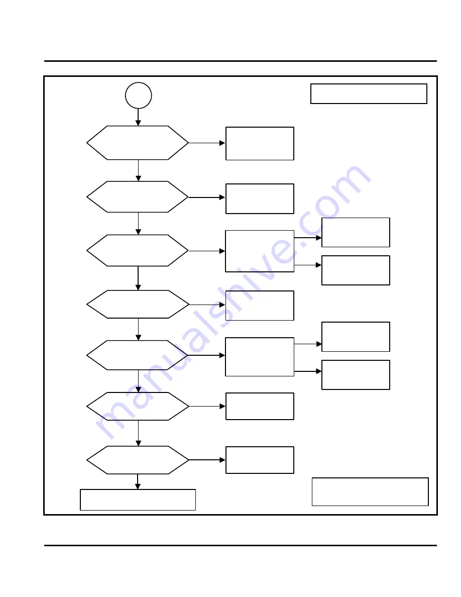
Figure 17. No Receiver Control Matrix
P
GSM_SEL and DCS_SEL
(from Magic IC)
signals are present on
Q110
Pin 3
and
Pin 1
?
NO
NO
NO
NO
NO
NO
NO
YES
YES
YES
YES
YES
YES
YES
RX275_GSM and RX275_DCS
signals are present on
Q110
Pin 4
and
Pin 6
?
RX275 signal is present
on
Q112 Pin 2
?
RF_V2 signal is present
on
Q112 Pin 3
?
RX_EN (from Whitecap
IC) signal is present on
Q112 Pin 4
?
Check
U800
See Note 1
Check
Q2102
See Note 1
Check
Q2101
See Note 1
Check
Q112
See Note 1
Check
U200
See Note 1
RX275_DPCS signal is
present on
Q2102 Pin 2
?
RX275_GSM_PCS signal is
present on
Q2101 Pin 2
?
GSM_SEL and DCS_SEL
signals are present on
Q110 Pin 1
and
Pin 3
?
See Note 1
RX CONTROL MATRIX functioning properly
END
Check
U900
See Note 1
Check
Q202
and
U200
See Note 1
VREF signal from U900
present on
C213
?
See Note 1
Check
U800
See Note 1
Check
Q110
See Note 1
NO
YES
NO
YES
In most cases, a reference board can be
used to compare signals.
Note 1: Check components for correct
orientation, cold solder joints, physical
damage, and functionallity.
Summary of Contents for 38C V100
Page 1: ...Level 3 Service Manual Model V100 GSM Technology Product Family 38C Personal Communicator ...
Page 2: ......
Page 73: ...V100 BOARD LAYOUT PAGE 1 2 ...
Page 74: ...V100 BOARD LAYOUT PAGE 2 2 ...
Page 77: ...V100 CONNECTOR SCHEMATICS ...
Page 78: ...V100 DISPLAY SCHEMATICS ...
Page 79: ...V100 FM SCHEMATICS ...
Page 81: ......
Page 83: ......


