background image

Sarix Professional 4 Bullet Camera Installation Manual

C6726M | 11/22

12

Initializing a Camera Username and Password

You must create a user with administrator privileges before the camera is operational. 

The new user can be created using the following methods:


l

Camera's web interface. Enter the camera's IP address in a web browser to access the web 
interface. For more information, see the Pelco Sarix Professional 4 Bullet Camera Operations 
Manual. If the camera is in the factory default state, you will be redirected to the New User page to 
create an administrator user:

 1.  Enter a new User Name or keep the default administrator name.

 2.  Enter a new Password for the user. It is recommended to use a secure and complex 

password.

 3.  Confirm the new password.

 4.  For the first user, Administrator must be selected in the Security Group drop-down menu.

 5.  Click Apply. After creating the user, you will be asked to login.


l

Camera Configuration Tool: discovered cameras that are identified by 

 will require a first user to 

be set. Select the Admin Users tab to create the first user. For more information, see the 

Camera 

Configuration Tool User Guide

.

Note

: Set up the first user through the camera's Web Interface or Camera Configuration Tool 

before you connect the camera to a VMS.

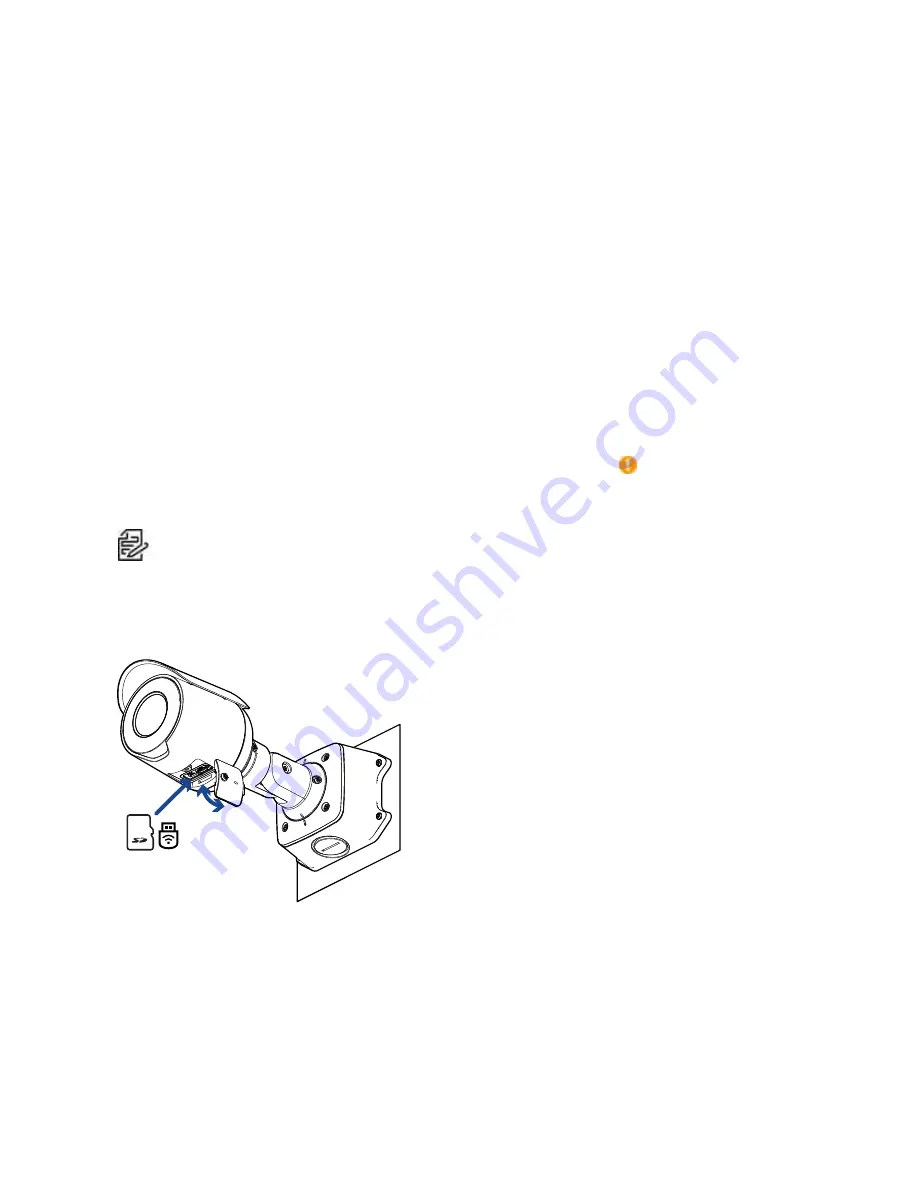
(Optional) Using the USB Wi-Fi Adapter

If you have a USB Wi-Fi Adapter (USB-AC56-**-MSI), attach it to the camera's micro USB port to access 
the camera's mobile web interface. 

After you connect to the Wi-Fi signal broadcast by the adapter, you can access the mobile web interface 
from any mobile device using the following address:

http://camera.lan   

For more information about configuring the camera from the mobile web interface see 

 USB Wi-Fi 

Adapter System User Guide

.

Summary of Contents for PELCO Sarix Professional 4

Page 1: ...Sarix Professional 4 Bullet Camera Installation Manual Document number C6726M Publication date 11 22...

Page 2: ...design trademark patent or other intellectual property rights of Pelco Corporation or its licensors Disclaimer This document has been compiled and published using product descriptions and specificatio...

Page 3: ...Panel Cover 11 Initializing a Camera Username and Password 12 Optional Using the USB Wi Fi Adapter 12 Assigning an IP Address 13 Setting the IP Address Using the ARP Ping Method 13 Accessing the Live...

Page 4: ...try to correct the interference by one or more of the following measures l Reorient or relocate the receiving antenna l Increase the separation between the equipment and the receiver l Connect the eq...

Page 5: ...mera to the junction box 2 Mounting hook slots Points to hold the camera to the junction box while connecting the required cables 3 Mounting holes Holes for securing the junction box to the mounting s...

Page 6: ...Server communication and image data transmission also occur over this connection The camera can either be powered by Power over Ethernet PoE or 12 VDC Aux 2 Serial number tag Device information produc...

Page 7: ...Optional Configuring microSD Card Storage 2 Micro USB port Accepts a micro USB to USB adapter Only required when using the USB Wi Fi Adapter 3 Link LED indicator Amber LED indicates if there is an ac...

Page 8: ...from inside the mounting surface install the junction box first After you install the junction box you can skip directly to step 3 of this procedure 1 Use the mounting template to drill four mounting...

Page 9: ...e connection from dust and moisture If PoE is not available the camera may be powered through the auxiliary power cable using either 12 VDC For more information see Connecting to Power and External De...

Page 10: ...ntation of the cable and boot matches the one shown in the image b Crimp the Ethernet cable onto the cord c Plug the Ethernet cable into the camera s Ethernet port d After you connect the cable to the...

Page 11: ...camera until it covers the junction box 10 Use the camera mounting screws to fasten the camera to the junction box Removing the Configuration Panel Cover 1 Use a T20 Pin In star shaped driver to unsc...

Page 12: ...e first user Administrator must be selected in the Security Group drop down menu 5 Click Apply After creating the user you will be asked to login l Camera Configuration Tool discovered cameras that ar...

Page 13: ...ARP Ping Method Complete the following steps to configure the camera to use a specific IP address Note The ARP Ping Method will not work if the Disable setting static IP address through ARP Ping meth...

Page 14: ...g the Camera Reference the camera s live stream as you aim the camera 1 Loosen the adjustment screw closest to the junction box to rotate the camera arm 2 Loosen the center adjustment screw to tilt th...

Page 15: ...buttons to manually adjust the focus Optional Configuring microSD Card Storage To use the camera s SD card storage feature you must insert a microSD card into the card slot It is recommended that the...

Page 16: ...ry power wire is distinguished by its thicker wire gauge and AUX PWR label The connection can be made with either polarity This product is intended to be supplied by a UL Listed Power Unit marked Clas...

Page 17: ...when connecting speakers and microphones as shown in the diagram 2 Yellow Audio Ground 3 Green Audio Output line level 4 Grey Ground 5 Red Digital Input 6 Pink Digital Output 7 Purple Reserved Wire do...

Page 18: ...f the below LED behaviors ensure that the camera is getting power and is using a good network cable before trying another solution LED Behavior Suggested Solution Green LED is off and amber is on Perf...

Page 19: ...nd hold the firmware revert button 3 Release the button after three seconds Do not apply excessive force Inserting the tool too far may damage the camera For More Information Additional information ab...

Page 20: ...www pelco com Pelco the Pelco logo and other trademarks associated with Pelco products referred to in this publication are trademarks of Pelco Inc or its affiliates ONVIF and the ONVIF logo are tradem...

Reviews: