


APX 8000XE M2
33
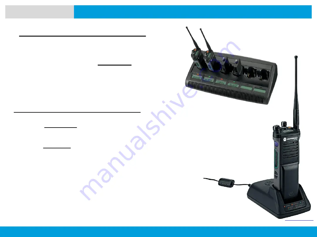
PREPARING YOUR RADIO FOR USE
Manually Terminating Reconditioning:
At any time during the reconditioning process
(
STEADY YELLOW
indication), remove and
reinsert the battery within
5 seconds
. This
causes the charger to terminate the
reconditioning process and begin the charging
process. The charger indicator changes to a
STEADY RED
.
Manual Reconditioning of the Battery
:
Within
2 ½ minutes
of the initial insertion of
an IMPRES battery (
STEADY RED
indication), remove and reinsert the battery
within
5 seconds
to manually force
reconditioning to occur. The charger indicator
changes from a
STEADY RED
to a
STEADY
YELLOW
. This forces the charger to
recondition and automatically recharge the
battery.
NOTE:
Excessive use of this feature
reduces the cycle life of the battery.


