background image

MoTeC USA   

Analysis 

10 


“i2” Analysis Math 

GPS data will have an inherent time lag.  The sequence of delays 

are from receiving real-time satellite signals, processing them, sending 
the data into the logger and the logger logging them.  MoTeC’s “i2” has 
a built-in “Corrected GPS” function found under the “Tools” pull down 
menu.  This function should only be used with data originating from a 
ADL2, SDL or ACL. 

Actual shift may vary.  You can use either the Auto function, or 

manually adjust the time delay.  The 10 Hz unit typically has a delay of 
approximately 130 msec.  The 20 Hz unit typically has a delay of 
approximately 110 msec.   

Summary of Contents for M GPS BL

Page 1: ...MoTeC USA GPS Part M GPS BL Available in 10 Hz or 20 Hz USER MANUAL Version 1 4...

Page 2: ...2008 The information in this document is subject to change without notice While every effort is taken to ensure correctness no responsibility will be taken for the consequences of any inaccuracies or...

Page 3: ...se 5 Speed Ready Output 5 Variable Voltage Option 5 Installation 6 GPS Receiver 6 Antenna 6 Loss of Signal 7 Connection 7 Connection to ADL2 SDL ACL 8 Connection to M400 M600 M800 9 Connection to ADL...

Page 4: ...re is more information to correctly identify your position with less error So it s easy to see the importance of your antenna having a clear line of sight to the satellites in the sky The system is a...

Page 5: ...F and DGPS lights indicate increased accuracy of the data With differential correction you will get the most accurate data Therefore best operation is achieved with these lights on 20 Hz Update Option...

Page 6: ...638 cm per pulse Speed Ready Output The speed ready output pin is pulled high to 5v when the speed signal is good and low to 0v when there is not enough data for accurate speed information The speed o...

Page 7: ...t or rear window For open wheeled cars on top of the roll hoop or just in front of the cockpit works best The antenna has a magnet base to hold itself onto a metal surface Any extra antenna wire can b...

Page 8: ...unit will loose track of those satellites being blocked When this happens a reacquisition will take place which can take some length of time Loss of signal can occur when driving under bridges The si...

Page 9: ...te rate channels should be logged at 20 Hz even though they only update at 10 Hz This will help minimize the time delay between when the data arrives to the logging device through the serial stream an...

Page 10: ...able to log the following channels of information Recommended Logging Rates Update Option 10 Hz 20 Hz GPS Speed 10 Hz 20 Hz GPS Heading 10 Hz 20 Hz GPS Altitude 10 Hz 10 Hz GPS Sats Used 10 Hz 10 Hz F...

Page 11: ...logger logging them MoTeC s i2 has a built in Corrected GPS function found under the Tools pull down menu This function should only be used with data originating from a ADL2 SDL or ACL Actual shift m...

Page 12: ...ing math expression for your speed pulse channel For the Motec ADL the built in Corrected GPS function can not be used All channels streaming through the RS 232 interface should have separate math exp...

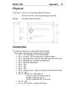
Page 13: ...data other messages available upon request Digital output pulse 0 5v with 50 duty cycle 94 Hz per 1 m s 940 Hz per 36 km h 1933 Hz per 46 mph 1 0638 cm per pulse can be connected to inputs which have...

Page 14: ...ly 6 to 18 volts allowed pin 2 Ground not 0v but ground or negative battery pin 3 Speed Ground optional internally connected to Ground pin 4 Speed Pulse connects to digital input pin 5 Speed Ready Sig...

Page 15: ...MoTeC Notes 14...

Reviews: