


8
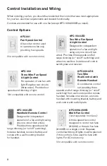
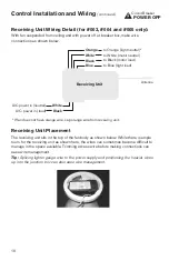
Control Installation and Wiring
When ordering your fan, you should have selected the control that was most appropriate
for your fan, electrical requirements and desired functionality.
Controls are intended for use with one fan (except #FC-009A/009B as noted).
Control Options
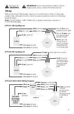
#FC-001
Fan Speed Control
A basic fan control used
to operate one fan only,
providing four speeds.
Not compatible with remote control.
#FC-009A/009B
Multi-Fan Control
(sold separately from fans)
A three speed fan control
designed to control two fans
(#009A) or three to five fans
(#009B) on a single circuit. Separate
control/switching of lights must be planned
if this control is to be used for fans with
lights. For AC motors only.
Not compatible with remote control.
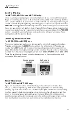
#FC-004-LED
Two Wire Fan Speed
& Light Control
Designed for independent
operation of a fan and light
using only one circuit (two
wires). Provides three speeds and full
range dimming (or “on/off” switching) and
wires into wall box. Includes wall control,
switch plate and receiver.
#FC-003-LED
Handheld Remote Control
Designed for independent
operation of a fan and light using
only one circuit (two wires).
Provides three speeds and full
range dimming (or “on/off” switching).
Includes handset, receiver, battery and
comes with a wall mounting bracket
for handset.
#FC-005-LED
Two Wire
Wall Control with
Remote Handset
A combination control
set providing three
speeds and full range dimming (or “on/off”
switching) from wall control and/or remote
handset. Includes one receiver, a remote
handset with mounting bracket, battery and
wall control with switch plate.
#FC-002
Three Wire Fan Speed
& Light Control
For operation of one fan with
light. Requires two circuits
(three wires). Provides four
speeds and dimming of light.
Not compatible with remote control.


