MORTARA INSTRUMENT SPECIFICATION
MIS-11-151-00 Rev. 1
© 2001 Mortara Instrument, Inc.
CONFIDENTIAL
PAGE 16 OF 26
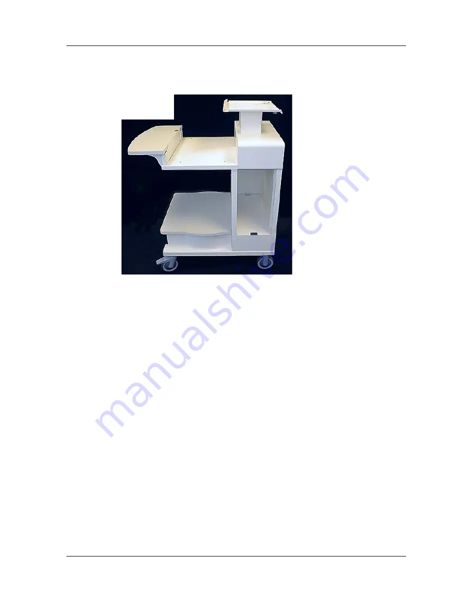
View of finished Cart, without Computer components.
Page 1: ...1 Page 1 of 26 Instructions for Assembling X Scribe II Cart COPYRIGHT 2001 BY MORTARA INSTRUMENT INC 7865 N 86TH STREET MILWAUKEE WISCONSIN 53224 MORTARA INSTRUMENT IS A REGISTERED TRADEMARK OF MORTA...
Page 2: ...nserting the Support Pins for the Writing Shelf 15 SECTION 2 INSTALLATION OF COMPUTER COMPONENTS 17 STEP 1 Installing Isolation Transformer 17 STEP 2 Installing Computer 18 STEP 3 Routing cables 18 ST...
Page 3: ...ase Assembly Plus the following Hardware ITEM 1 1 4 WING NUT 2 EA ITEM 2 1 4 SLOTTED TRUSS HEAD SCREW 2 EA ITEM 3 6 3 4 82 COUNTERSUNK FLAT 3 EA HEAD PHILLIPS SCREW ITEM 4 8 5 8 PAN HEAD PHILLIPS SHEE...
Page 4: ...ORTARA INSTRUMENT SPECIFICATION MIS 11 151 00 Rev 1 2001 Mortara Instrument Inc CONFIDENTIAL PAGE 4 OF 26 Keyboard Shelf Item 15 Keyboard Shelf Support Item 17 Writing Shelf Item 18 Gusset 2 ea Item 1...
Page 5: ...ORTARA INSTRUMENT SPECIFICATION MIS 11 151 00 Rev 1 2001 Mortara Instrument Inc CONFIDENTIAL PAGE 5 OF 26 Side Cover Item 19 Rear Cover Item 22 Column Cover Item 21 Isolation Transformer Cover Item 20...
Page 6: ...STRUMENT SPECIFICATION MIS 11 151 00 Rev 1 2001 Mortara Instrument Inc CONFIDENTIAL PAGE 6 OF 26 Printer Shelf Item 23 Base Assembly Upper Column Assembly Item 24 Item 25 Castors shown for reference o...
Page 7: ...he Keyboard Shelf Item 15 on a flat surface with the side with 4 holes facing up Position the Gussets Item 16 as shown and affix with Qty 4 8 x 5 8 Pan Head Phillips Sheet Metal Screws Item 4 Position...
Page 8: ...Mortara Instrument Inc CONFIDENTIAL PAGE 8 OF 26 STEP 2 Placement of Cable Clips Position the Cable Clips Item 13 as shown on the bottom of the Printer Shelf Item 23 The Cable Clips will be used late...
Page 9: ...STEP 3 Unpacking Upper Column and Base Assembly NOTE TWO PEOPLE RECOMMENDED FOR THIS STEP Have an assistant hold the Upper Column Assembly Item 25 as the two 5 16 Detent Ring Pins Item 11 are removed...
Page 10: ...Item 25 on its back Place Keyboard Shelf Assembly as shown and affix with Qty 4 M4 x 8mm Pan Head Phillips Machine Screws Item 7 Keyboard Shelf Assembly Place the Printer Shelf on the support tubes a...
Page 11: ...th an assistant lay the Base Assembly Item 24 on its back on a soft clean surface Affix the Castors as shown using Qty 16 M8 x 16 mm Pan Head Phillips Machine Screws Item 6 and a 4 Phillips Screwdrive...
Page 12: ...Base NOTE 2 PEOPLE RECOMMENDED FOR THIS STEP With an assistant lift the Upper Column Assembly Item 25 and position as shown onto the Base Assembly Item 24 Slide the rear set of fixed 5 16 Roll Pins lo...
Page 13: ...til the rectangular tubes are fully engaged with the rear tabs of the Base Assembly Item 24 Install Qty 2 5 16 Detent Ring Pins Item 11 through the holes in the Base Assembly and Upper Column Assembly...
Page 14: ...ortara Instrument Inc CONFIDENTIAL PAGE 14 OF 26 STEP 7 Ground Strap Attach the Ground Strap Item 13 to the M6 Studs using M6 Star Washers Item 5 and M6 Hex Nuts Item 10 Tighten using a 10mm wrench to...
Page 15: ...CONFIDENTIAL PAGE 15 OF 26 STEP 8 Inserting the Support Pins for the Writing Shelf Install Writing Shelf Item 18 by sliding slot in bracket over the two inner Shoulder Bolts Item 8 Insert Qty 4 3 16...
Page 16: ...MORTARA INSTRUMENT SPECIFICATION MIS 11 151 00 Rev 1 2001 Mortara Instrument Inc CONFIDENTIAL PAGE 16 OF 26 View of finished Cart without Computer components...
Page 17: ...ck input and output voltage settings on Isolation Transformer Ensure the power switch is in the on position Orient the Isolation Transformer with the power entry module facing you Using caution slide...
Page 18: ...omputer Determine which direction the front of the computer will face Slide the computer into the opening accordingly STEP 3 Routing cables Connect the power cables to the Isolation Transformer Route...
Page 19: ...Wing Nut Item 1 Push the Monitor Lock Clip against the base of the monitor and tighten the Wing Nuts Item 1 There should be some deformation of the clip as it is tightened STEP 5 Monitor Cables Route...
Page 20: ...Transformer opening by similarly inserting the two tabs in the frame and fasten with Qty 2 M4 x 8mm Pan Head Phillips Machine Screws Item 7 Note To avoid pinching of the power cables make sure that th...
Page 21: ...y install the Rear Cover Item 22 by placing the two slots over the tabs located on the top of the back panel of the Upper Column Assembly Item 25 Secure the Rear Cover by using Qty 3 M4 x 8mm Pan Head...
Page 22: ...MORTARA INSTRUMENT SPECIFICATION MIS 11 151 00 Rev 1 2001 Mortara Instrument Inc CONFIDENTIAL PAGE 22 OF 26 COMPLETED X SCRIBE II SYSTEM Shown with both a Z200 Printer and a Laser Printer...
Page 23: ...IONAL ACCESSORIES COVER SHELF INSTALLATION TO BE USED WITHOUT A Z200 PRINTER COMPONENTS Tools required for Assembly 1 Phillips screwdriver 2 Material Supplied with Cover Shelf Installation Cover Shelf...
Page 24: ...ssembly remove it Refer to page 21 Install the Cover Panel Item 2 from the back side of the Upper Column Assembly as shown Fasten the Cover Panel Item 2 by using Qty 2 M4 x 8mm Pan Head Phillips Machi...
Page 25: ...iting Shelf Item 4 or if there is a gap between the two shelves it is possible to adjust the Cover Shelf Finally reinstall the Rear Cover on the Upper Column Assembly Refer to Page 21 Install the Writ...
Page 26: ...2 Material Supplied for Patient Cable Installation ITEM 1 M4 x 8 mm PAN HEAD PHILLIPS MACHINE SCREW 1 EA ITEM 2 CABLE CLAMP 1 EA When a Mortara Instrument EPC and corresponding M12 Patient Cable are u...