1
Morrison Bros. Co. ‑ Dubuque, IA ‑ 800‑553‑4840
918AC‑0160 PP
!
!
Rev. 09-27-2022
918AC Series Expansion Board
Installation, Operation, and Maintenance Instructions
The 918AC Expansion Board is designed to provide additional output configurability to the 918AC series
System Interface. The additional output configurations include: non-persist, auto-timeout with configurable
timeout value, and latching modes.
Failure to follow any or all of the warnings and instructions in this document could result in a hazardous
liquid spill, which could result in property damage, environmental contamination, fire, explosion, serious
injury or death.
Le fait de ne pas se conformer à l’un ou l’autre des avertissements ou à l’une ou l’autre des directives
apparaissant dans ce document pourrait donner lieu à des déversements de liquides dangereux, lesquels
pourraient engendrer des dommages matériels, des risques de contamination environnementale,
d’incendie ou d’explosion, des blessures graves ou la mort.
Contents
Installation..........................................................................................................................................1
Steps to Configure the 918AC Series System Interface Motherboard ..............................................
2
Non-Persist Output Function ........................................................................................................
2
Auto-Timeout Output Function ....................................................................................................
3
Latching Mode Output Function ..................................................................................................
4
DIP Switch Configuration Tables ....................................................................................................
6
Installation
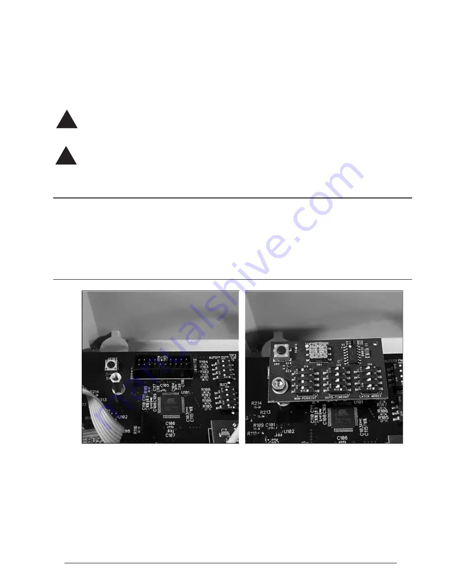
Figure 1 - Standoff and Module Installation
1. Turn off the power to the 918AC Console.
2. Remove and retain the screw that is in the 918AC Motherboard, located to the left of the P101 connector and
below the reset button. It is the same location in which the standoff is installed in Figure 1.
3. Install the standoff provided in the kit into the same threads the screw was in, shown in Figure 1.
4. Install the 918AC Expansion Module by plugging it into the P101 connector on the 918AC Motherboard
with the orientation shown in Figure 1.
NOTE: If the 918AC Expansion Module does not fit correctly, do not force it. First, verify the
orientation of the expansion board shown in Figure 1. Then check that the motherboard version
is compatible. Compatible motherboards will have a pin removed corresponding to the keyed
pin on the expansion module.


