19
MorrHeat - Most Heat In The Industry - Rev 3/18/2019
Page 1: ...Installation operation and service instructions 120v Manual Waste Oil Fired Boiler 280 480...
Page 2: ...uel Supply Lines Page 14 Boiler Assembly Wiring Page 16 Boiler Assembly Installation Page 22 Oil Burner Technology Page 23 Oil Burner Components Page 24 References Nozzle Electrode Burner Pump Page 26...
Page 3: ...sion of the metals the equipment is constructed of this would void the warranty Antifreeze does not burn and will interrupt the performance of the unit and potentially shut down completely until re pr...
Page 4: ...ontaminates be aware of needing to change filters when needed Keep the chamber and heat exchanger s passageways clean Make sure the fuel pump is primed and lines are free of any debris air bubbles or...
Page 5: ...Pump Watts 1 212 Weight Lbs 36 5 Oil Primary Amp 0 2 Oil Valve Amp 0 075 Pre Heater Block Amp 4 2 Pre Heater Controller Board Amp 0 011 Igniter Transformer Amp 0 3 Burner Motor Amp 3 6 Voltage 120v Cy...
Page 6: ...he I B R provisions governing forced draft conditions 0 10 inch W C positive pressure at the boiler flue gas outlet Net ratings are based on piping and pickup allowance 1 15 I B R Vent Diameter size i...
Page 7: ...ey may be used with burners firing gas or oil Boiler Burner units operate with a positive pressure overfire and may be vented using a conventional chimney with a balanced draft or pressurized vent sys...
Page 8: ...installed in flue passages 2 Wood pallet with shrink wrapped boxes A Box of jacket parts B Box marked 1 Manifold Box a Supply and return manifold with gaskets mounting studs nuts and and washers b Ret...
Page 9: ...minimum clearances outlined in Fig 1 Remember to allow room for the boiler door to open with the burner mounted 4 Make sure that the surface on which the boiler is to be installed is capable of suppo...
Page 10: ...ch opening shall have at least 1 sq inch free area per 1 000 btn hr of burner input Opening should freely connect with areas having adequate infiltration of outside air When air comes directly from ou...
Page 11: ...4 1 2 33 4 1 2 33 2 B As Required 2 1 2 Boiler Supply Connection Boiler Vent Connection BOILER MODEL VENT CONNECTION DIA DIMENSIONS MHB280 10 42 MHB360 10 52 MHB480 10 57 Notes 1 Dimensions as per jo...
Page 12: ...ft occur install a barometric draft regulator Boiler operates with positive pressure overfire Chimney provides negative pressure that is balanced with a barometric draft control Boiler breech stub ven...
Page 13: ...d party draft inducer or power vent may be needed to prevent back draft from occurring not provided 3 Install a barometric damper NOT included in the stack only if the draft up the stack exceeds 08 Dr...
Page 14: ...fuel pump assembly to the heating unit Ferrule fittings are not recommended and Teflon tape is not needed Using a Teflon tape or liquids that dry on the threads in creases the potential of creating a...
Page 15: ...t in accordance with A S M E cod and authorities jurisdiction 3 Attach quadrant locking damper and seal with High Temperature silicone sealant SUPPLY MANIFOLD KEY 1 Probe Type LWCO 2 Modulating Aquast...
Page 16: ...be compatible with the electricity furnished at job site 2 Wiring diagram is found in burner instruction manual Follow diagram for proper wiring of burner and controls 3 Where burner motor voltage di...
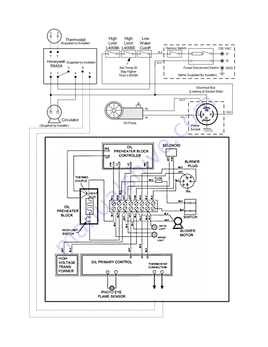
Page 17: ...lectrical continuity is created between terminals 3 and 4 energizing the circulator for that zone At the same time electrical continuity is created between terminals 5 and 6 on the R845A creating a cu...
Page 18: ...18 MorrHeat Most Heat In The Industry Rev 3 18 2019 Example1 Example2...
Page 19: ...19 MorrHeat Most Heat In The Industry Rev 3 18 2019...
Page 20: ...ustry Rev 3 18 2019 Fig 35WiringDiagram ZoneWiringUsingHoneywellV8043FValves Factory Boiler Wiring Not Shown Fig 33 Fig 34 Fig 36WiringDiagram CirculatorZoneWiringUsingHoneywellR845A s Factory Diagram...
Page 21: ...mounted in the proper location and proper direction of oil flow CAUTION Oil supply pressue to Burner Pump must not exceed 3 PSI per NFPA Code DO NOT USE TEFLON TAPE OIL PUMP OIL FILTER FRENCH IN FLOOR...
Page 22: ...factory 1 Postion boiler on proper load bearing concrete pad on floor 2 Attach supply manifold as shown in Figure 10 FIG 10 SUPPLYMANIFOLDASSEMBLY FIG 11 RETURNDIFFUSERINSTALLATION Boiler Supply Port...
Page 23: ...ific temperature setpoint Then compressed air from the air compressor is infused with the oil prior to spraying out the nozzle by breaking up the oil particles into a finer mist or spray The electrode...
Page 24: ...y will shutdown the oil burner To restart the unit reset the red button on the oil primary Hard lock out may require holding the reset for 30 45 secs Oil Pre Heater Block Pre heats the oil and air bef...
Page 25: ...ssure going to the pre heater block Should be adjusted between 8 PSI and 14 PSI as indicated on the Air Pressure Gauge Oil Filter With Housing The fuel filter with housing allows an easy spin on off f...
Page 26: ...Pre Heater Control Board Pre Heater Oil Block Electrodes Nozzle Burner Pump Assembly 3 8 from tip center of nozzle flush with the Electrodes Electrodes 3 16 even between Electrodes Heat Rod Transform...
Page 27: ...l open position let water flow through the system by opening the drain cocks so water can exit the system through a hose an in 1 above When the system seems to be full and free of air close the drain...
Page 28: ...rements An under sized expansion tank will cause system water to be lost through the relief valve and make up water to be introduced though the fill valve Continual introduction of fresh water into th...
Page 29: ...A service representative may also be required by the local utility on gas fired equipment Instruction regarding the proper care and maintenance of the unit should be outlined with these people presen...
Page 30: ...or continual relief valve operation since continual make up water will reduce boiler life Where freeze protection is required to use antifreeze made especially for hydronic systems such as inhibited...
Page 31: ...mbly 8 After the oil in the pre heater block has hit the desired temperature while the burner is running briefly jump the F terminals on the oil primary to allow the burner to run during the fuel pump...
Page 32: ...schedule Every end user will have a little different schedule with all factors considered for every location and application Check or change oil filter Check or change air filters Clean flame cone if...
Page 33: ...require additional sealing 3 Observe burner operation for excessive noise or vibration 4 Check for water leaks Boiler which operate only for heating need only be cleaned at the end of each heating sea...
Page 34: ...on of flue baffles and replace as needed 7 Check front door and flue collector rope seals replace as needed 8 Re assemble and put boiler into operation as needed NOTE When the boiler is to be layed up...
Page 35: ...e so tighten all fitting and tighten the unused intake port plug Also check the filter cover and gasket Also check the pump filter and clean it with a brush and fuel oil or kerosene if it looks dirty...
Page 36: ...estrictions or leaks Pull compressor cover and inspect carbon vanes May need to replace Check filter clean if needed 4 Reduced air pressure and can t increase Gauge may be bad Intake filter muffler is...
Page 37: ...ount of ash and won t allow sufficent draft Pump not functioning properly over firing May need RPM readjust Reset flame slightly less than 1 2 way down tube combustion chamber Use adjustment knob on p...
Page 38: ...hat the four extension setscrews 043 protrude through the insulation 6 Attach rear jacket panels 036 and 038 to the 2 extensions screws 043 using the M6x10 pan head screws Screw teh rear panels togeth...
Page 39: ...Boiler 033 Center Panel 036 Right Rear Panel 038 Left Rear Panel 040 Insulating mat for boiler shell 041 Upper front trim panel 043 Setscrew AF 17 rear jacket panel spacer piece 060 Rear insulating m...
Page 40: ...ose coupling nipple 1 4 025 Sight glass with seal 026 Sight glass and measing tube cap 026A Sight glass nipple 1 1 4 027 Burner plate 028 Stopper 2 030 Cleaning tools complete 031 032 043 Jacket space...
Page 41: ...n The Industry Rev 3 18 2019 170 052 053 100 043 022 051 053 056 056 019 004 062 005 047 010 046 062 054 056 017 002 032 031 030 028 012 028A 025 026 048 027 049 024 023 013 014 016 028 003 005 004 00...
Page 42: ...etermine if the defect can be repaired or a complete unit swap is necessary Pictures of the unit and potential defect will be required All returned items must be approved by MorrHeat and returned with...
Page 43: ...e or over heated unit Neglected maintenance and cleaning the unit is another direct cause to over firing or over heating the unit Keep your unit clean and maintained properly for best performance and...