background image

Page 40

Perforating

CREASING / BOOKLET MAKING

FIG 16.2

FIG 16.1

*Perforator stripper

78-013

All of the blades and anvils are supplied with fixings.

Standard Part Number

*It is recommended that for multiple perforations, a separate perforator stripper is used for

every perforating blade set fitted in the creasing unit.

1. Turn the mains supply to the machine ‘off’.

2. Remove the stacker unit and open the exit guard.

3. Locate and remove the blades / anvils from the despatch kit supplied with the

machine.

4. Using the 2mm allen key (supplied), loosen the drive wheel that is to accommodate

the blades.

5. Slide the drive wheel away from any obstructing drive wheels or hubs in order to

mount the blades.

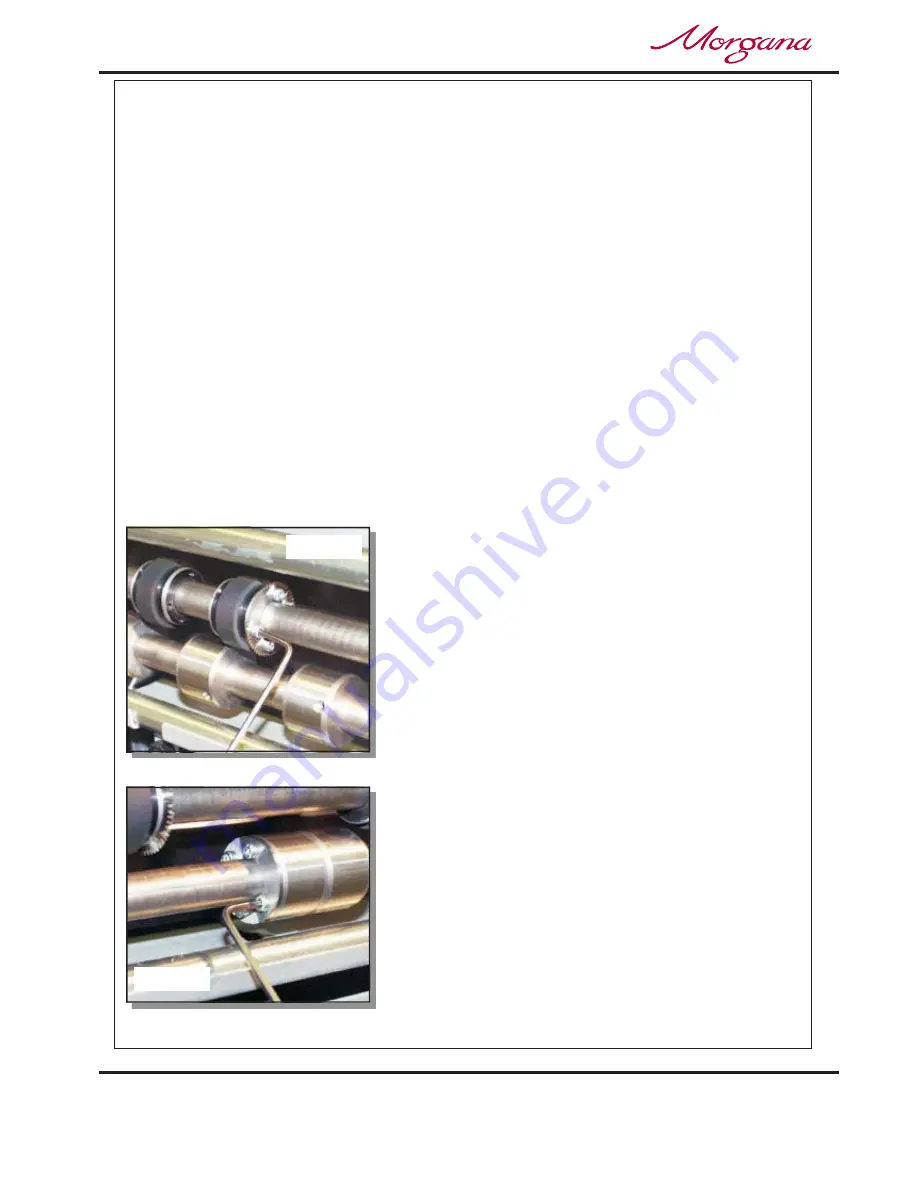
6. Using the 2.5mm allen key (supplied), take one

half of the matching pair of blades and mount on
to the drive wheel. Do not secure the blade.

7. Mount the other half of the blade to the drive

wheel as shown (fig 35.1). Secure the blades to
the wheel ensuring not to over tighten grub screw.

8. Mark on a single sheet the desired perforating

position. Feed the sheet through the machine

manually until the mark can be seen. Use this
mark to assist in fixing the position of the
perforating drive wheel to the roller drive shaft.

9. Using the 2mm allen key, loosen the drive hub

nearest the perforating drive. Slide the drive hub
away from any obstructing drive wheels or hubs
in order to mount the anvils.

10. Using the 2,5mm allen key, take one half of the

matching pair of anvils and mount to the drive
hub. Do not secure the anvil.

Setting the machine

Summary of Contents for Documaster MK3

Page 1: ...G AUTOMATIC BOOKLET MAKING MACHINE Creasing Unit OPERATORS MANUAL Part 1 FROM SERIAL No 780156 ONWARDS Documaster MK3 Website www morgana co uk 70 111 Morgana Systems Limited United Kingdom Telephone 01908 608888 Facsimile 01908 692399 ...

Page 2: ... Wheels and Hubs Setting the Stacker Assembly Programming the machine for Creaser Operation Setting the Feed Setting the Batch Quantity Setting the Crease Positions Storing the Crease Positions Running the machine Reading Stored Programs Paper Jamming Setting the Machine to Run in Manual Mode Adjusting the Paper Guides Adjusting the Sliding Back Stop Programming the machine for Booklet Maker Opera...

Page 3: ...PRODUCT RECYCLING DISPOSAL 55 Storing the Program Running the Machine Reading Stored Programs Clearing Booklet Sheets from the Booklet Maker Infeed Tray Using the Booklet Maker in Manual Mode Hand Feed Using the Optional Camera Recognition System Fixed Data Using the Optional Camera Recognition System Variable Data Equipment spares Setting the machine Setting the blade pressure Setting the blade a...

Page 4: ...rom trailing edge 30 0mm 1 2 Production up to 5000 sheets hour one crease on A4 sheet CREASER UNIT SPECIFICATION The Morgana DocuMaster MK3 is a fully automatic suction feeding creasing booklet making system designed for use with both conventional litho and digital printers the operating environment should be controlled to a temperature between 10 The system comprises a creasing unit linked to a f...

Page 5: ...4 Minimum staple pitch 115mm 4 5 Maximum number of sheets in book 20 sheets 80 gsm Maximum cover weight up to 350 gsm Minimum inside sheet weight 80 gsm Maximum trim 25mm 1 For optimum performance the difference between the cover and the inside sheet should be no more than 110 gsm Production up to 1560 books hour dependant on number of sheets in book DocuMaster MK3 ...

Page 6: ...se hair Do not under any circumstances adjust the paper gate when the machine is switched on REGLES DE SECURITE A FAIRE ET A NE PAS FAIRE Lire ce mode d emploi avant d utiliser la machine Respecter l alimentation électrique indiquée Brancher sur une prise séparée car une surcharge peut entraîner un incendie ou un choc électrique Installer le cordon d alimentation de manière à ne pas pouvoir trébuc...

Page 7: ... rotating rollers Do be aware of low current anti static shock Attention au risque de se coincer les doigts et aux pièces en mouvement lors du fonctionnement de la machine Ne pas porter de vêtements flottants lors de l utilisation de la machine Rassembler les cheveux longs lors de l utilisation de la machine Attention au risque de se coincer les doigts et aux pièces en mouvement lors du fonctionne...

Page 8: ...Page 8 CREASING BOOKLET MAKING BLANK PAGE ...

Page 9: ...er tilt handle 6 Air separation knob 11 Paper Gate 2 Stacker assembly 7 Adjustable side lay 12 Exit Guard 3 Suction slot knob 8 Back stop 13 Vacuum Bleed Knob 4 The control panel 9 Fixed side lay 14 Display 5 Air distribution knob 10 Roller tilt knob 15 Anti Static Unit DocuMaster MK3 DocuMaster MK3 ...

Page 10: ...he Display Unit and the Switches on the Control Panel allow the operator to read edit create and initiate numerous creasing programs within the memory The Control Panel houses the Selection Switch Compressor switch System switch and an industry standard Emergency Stop switch which will stop all power going to the machine when activated ...

Page 11: ...scroll through stored addresses and programs increase or decrease the batch quantity and set a crease position When activated the system switch will operate the motors in order to begin the creasing sequence Allows the operator to switch off the compressor unit in order to utilise the machine to manually feed sheets DocuMaster MK3 ...

Page 12: ...djustment of the paper gate is 6 5mm 1 4 away from the mounting block Turn disc J to make this adjustment This setting is only intended as a guide for instance sheets with an upward curl will require this setting to be in creased Set the height of the Paper Gate to approximately two thicknesses of paper by turning knob K An excessive gap is a most likely cause of double sheet feeding Setting the S...

Page 13: ...ir distribution knob can be rotated to various positions in order to supply air to different ports Position 1 is recommended for most sheet sizes However a better result may be obtained by using the settings below or by experimentation For A5 sheets or 8 inches long front port and port 1 open For A4 sheets or 11 inches long front port and port 2 open For A3 sheets or 17 inches long front port and ...

Page 14: ...e that the media is accurately driven and supported through the rollers The drive wheels and hubs are fixed to the rollers by means of a grub screw To locate this grub screw the rollers can be rotated by operating the motor manually To operate the motors manually switch the machine on at the Emergency Stop switch Following the arrows on the display unit move the selection switch to the left to sel...

Page 15: ...n the stacker unit a left handed guide and a right handed guide The guides will control the way in which the paper is collated by setting their positions on the stacker bed 2 Place a single sheet from the stack to be creased perforated on to the stacker bed against the left hand guide 3 Position the right hand side guide on to the stacker bed leaving a minimum clearance of approximately 1mm each s...

Page 16: ...ed set the distance between the top of the sheet and the backstop flanges to approximately 5mm 5 For shorter sheets the back stop can be used as shown in FIG 13 1 to adjust the position of the paper stack TIPS The magnetic back stop supplied with the machine can also be used as a tool holder as demonstrated In the photograph left ...

Page 17: ...ook Set Feed Reset Mode to Autocreaser Mode to Autocreaser Setup Long Pulse Medium Pulse Short Pulse Stream Feed Select A typical Autocreaser display menu is shown below IMPORTANT Programming the machine for Creaser operation 1 Switch the power on by turning the Emergency stop button clockwise to release the safety latch The display is now switched on and will be as shown below If you have not bee...

Page 18: ...anti clockwise to adjust the batch quantity in increments of 5 5 Move the selection switch up one click at a time until the start up menu is displayed A typical start up display menu is shown below i Move the selection switch to the right to select ii Move the selection switch to the right one click at a time selecting until the display shows as shown below iii Following the arrows on the display ...

Page 19: ...ase position move the selection switch down the 2nd crease is selected and can be set as described in steps iv to vi above Crease positions can be set in increments of 0 1mm Further creases can be set in this way up to a maximum of nine creases viii When the required creases have been set move the selection switch up one click at a time until the display contains the word see below 6 Once the crea...

Page 20: ...vent of a paper jam occurring whilst the machine is operating the display will read In order to remove the paper causing the jam move the selection switch to the left or to the right to drive the paper forwards or backwards in short pulses In order to feed heavy stock very small or very large sheets embossed or even irregular shaped sheets it may be required to operate the machine manually The mac...

Page 21: ...Page 21 SYSTEM BLANK PAGE DocuMaster MK3 ...

Page 22: ...justing the Sliding Back Stop Inse he infeed tray of the Booklet Maker Adjust the width of the paper guides by sliding the lever on the underside of the infeed tray forwards or backwards until the sample sheet slides freely in the guides With the sample sheet in its downward resting position adjust the sliding back stop until it is approximately 5mm to 10mm clear of the back edge of the sample she...

Page 23: ...We recommend that you either seek training or ask a trained operator to run the machine for you Move the selection switch to the left to select only if you have been trained to operate this machine If you have not been trained to operate this machine and you select Morgana Systems Ltd accept no responsibility for personal injury damage to the machine or damage to materials being processed by the m...

Page 24: ...creases less than 32mm from the leading edge of the paper Once set these sizes can be adjusted as required by following steps 5B to 11 Setup Long Pulse Medium Pulse Short Pulse Stream Feed Select Long Pulse Medium Pulse Short Pulse Stream Feed NOTE NOTE ii Move the Selection Switch down to select the required sheet size and then move the Selection Switch to the right to select as described on page...

Page 25: ...itch clockwise to increase or anti clockwise to decrease vii The can now be set as follows Move the Selection Switch to the left to select or to the right to select The or whichever has been selected can then be adjusted by rotating the Selection Switch clockwise to increase or anti clockwise to decrease Sheet Length Tens Decimals Tens Decimals Book Centre Tens Decimals Tens Decimals Sheet Width T...

Page 26: ...clockwise the display will show Sheets in Book Variable Data as shown on next page This setting is used when the optional Camera Recognition System is fitted and the number of sheets in the Booklet are variable Setting the Crease Style ii Move the selection switch to the right one click at a time selecting until the display contains the words More Crease Style 6 From the Booklet Maker start up men...

Page 27: ... iv Move the selection switch to the right to toggle between and v If has been selected move the selection switch down and then rotate the selection switch to adjust the hinge position Crease Style Cover Only Cover Centre All Sheets None Select More Cover Crease Hinges are ON Hinges are OFF Hinges are ON Setting the Cover Crease iii Move the selection switch down 7 From the Booklet Maker start up ...

Page 28: ... Set the to double the length of the finished document i e If the finished document is 210mm see FIG 2 below set the sheet length to 420mm See page 24 for setting the sheet length More Stitch Pos Stitch Pos Sheet Length iv The Offset From Booklet Centre can now be adjusted by rotating the Selection Switch clockwise to increase or anti clockwise to decrease 8 From the Booklet Maker start up menu th...

Page 29: ...se Style None Edge Stapling ii Move the selection switch to the right one click at a time selecting until the display contains the words iii Move the selection switch down to select the ype iv Move the selection switch to the right to select Setting the Set Knock More Set Knock Set Knock t Long Knock Double Knock PreStitch Delay Pre Fold Delay Select 9 From the Booklet Maker start up menu the can ...

Page 30: ...ch causes the infeed sidelays to hold useful if the booklet is not being folded square however it is essential that the sheet width is set accurately Selects double knock which causes the infeed sidelays to actuate twice prior to stapling This ensures that the booklet is jogged into a uniform book This adjusts the time delay between the side knock and stapling this is sometimes useful in ensuring ...

Page 31: ...he left to select or to the right to select The or whichever has been selected can then be adjusted by rotating the Selection Switch clockwise to increase or anti clockwise to decrease 11 Trim Length Tens Decimals Tens Decimals Setting the Batch Quantity Storing the Program Feed Setup This function is not available in the Booklet Maker Mode of operation 12 The booklet maker settings can now be sto...

Page 32: ...to the right to select ii Move the selection switch to the right one click at a time until the display contains the word iii Move the selection switch down to select iv Move the selection switch to the right to select v Rotate the selection switch clockwise or anti clockwise to select to and view the program settings More Programs Save Settings Select Yes No 1 For Settings and Adjustments to the B...

Page 33: ...e switch on the Square Back System is set in the position shown below All Sheets Cover Centre Cover Only None NOT i From the Booklet Maker start up menu move the selection switch to the left to select ii Move the selection switch down one click at a time selecting until is selected If the display reads move the selection switch to the right to change it to iii Feed the booklet sheets by hand into ...

Page 34: ...et 3 Sheet 4 4 Sheet Booklet Using The Optional Camera Recognition System If Fitted and the number of sheets in each book are the same i e Fixed Data Programme the machine for Booklet Maker operation as described on pages 22 to 32 and then operate the Camera Recognition System as follows NOTE ii Move the selection switch to the right one click at a time selecting until the display contains the wor...

Page 35: ...ptured can now be set by rotating the Selection Switch clockwise to increase or anti clockwise to decrease vii The of the image to be captured from the leading edge of the sheet can now be set as follows Move the Selection Switch to the left to select or to the right to select The or whichever has been selected can then be adjusted by rotating the Selection Switch clockwise to increase or anti clo...

Page 36: ...mm 10 mm Hinge FIXED DATA If there is no image on the sheet at 90mm from the leading edge of the sheet then another position greater than 90mm must be set Limitations to the positions of the captured image are pre set in the software and cannot be exceeded See Below An Image template is provided with the camera recognition system kit to assist in showing the possible area of the image that can be ...

Page 37: ...ine and the camera will be activated to capture and store the required image xiii The display will show that the image has been captured as shown below xiv Move the selection switch up one click at a time until the display contains the word xv Load the booklet stack onto the feed bed and then run the job by switching the Compressor and System Switches on and then move the selection switch down to ...

Page 38: ...he selection switch is moved up until the display contains the word the display will read as shown below 3 Load the booklet stack onto the feed bed and then run the job by switching the Compressor and System Switches on and then move the selection switch down to select Sheets in Book Variable Data Limitations of the position of the Image to be captured on the sheet Feed NOTE NOTE The default posit...

Page 39: ...ch kit supplied with the machine they are listed below 1 off Set of standard perforation 56 tooth blades 1 off Set of standard hardened anvils 1 off Perforator stripper 1 off Scoring wheel 1 off 3mm bondhus wrench allen key 1 off 2mm bondhus wrench allen key The perforator blades are split into two matching halves and are fitted to the drive wheels as shown in the photograph using the four screws ...

Page 40: ... order to mount the blades 6 Using the 2 5mm allen key supplied take one half of the matching pair of blades and mount on to the drive wheel Do not secure the blade 7 Mount the other half of the blade to the drive wheel as shown fig 35 1 Secure the blades to the wheel ensuring not to over tighten grub screw 8 Mark on a single sheet the desired perforating position Feed the sheet through the machin...

Page 41: ...adjacent to the drive wheel and blade as shown 15 Operate the machine and test the perforations for form For multiple perforations repeat the above procedure Demonstrates a typical set up for perforating sheets Perforating drive wheel with mounted blades Drive hub with mounted anvils Perforator stripper Standard drive hub Standard drive wheel It is important that the drive hubs are arranged evenly...

Page 42: ...ction switch to the left to select iii Move the selection switch down to select iv Press the system switch down v Move the selection switch to the right the machine will activate and the blade will move to top dead center The display will now read and then change to read 2 Raise the exit guard 3 Using a 6mm allen key unlock the shoulder bolts labelled with scale transfer positioned at each end of ...

Page 43: ...the stacker unit from the machine 2 Unlock and centralise the roller tilt mechanism in order to locate the heads of the front alignment screws 3 Using a 3mm allen key loosen the cap head type locking screws located on the front face at both ends of the blade anvil as shown below 4 Using a 4mm allen key locate the two front or back alignment screws in the side frame in order to adjust the blade anv...

Page 44: ... and lay it on a flat surface 6 Slide the adjustment links away from the dowels located in the ends of the blades anvils as shown in the photograph left 7 Place the new blade set into position Check that the eccentric shoulder bolts on the link plates have been positioned as shown in fig 20 1 8 Upper blade anvil only Slide the adjustment links onto the dowels 9 Slide the new blade set into the slo...

Page 45: ...owever components within the blade set can not be ordered separately ie single blade or anvil Consisting of a standard blade and anvil blade brushes blade links and alignment bolts Consisting of a narrow blade and anvil blade brushes blade links and alignment bolts If the pressure and the alignment of the crease is not to a satisfactory level see pages 42 43 to adjust the creasing line Standard Bl...

Page 46: ...that the emergency stop button has been released Check that the exit guard is down Check that the stacker unit is located correctly and has not been disconnected from the magnetic switch Check that the lower blade anvil is connecting to the home switch mounted below the lower blade anvil Check that the paper stack is not too high or too heavy for the feeder The height of the paper stack should be ...

Page 47: ...om in feed roller drive belt If at any time during the creasing process the control panel reads it is indicating that the lower blade anvil has not made contact with the HOME switch ie blade still in top position Switch the machine off and remove the blade set and ensure that the area is free from obstructions Return the blade set to the creasing unit and switch the machine on Operate the machine ...

Page 48: ...re fitted on the Main Control board of the Booklet Maker Unit This will reset the Booklet Maker Unit back to default factory settings and should only be used as a last resort 1 From the Booklet Maker start up menu move the Selection Switch to the left to select 2 Move the Selection Switch down to select 3 Move the Selection Switch to the right to select 1 From the Booklet Maker start up menu selec...

Page 49: ...on Cable is Plugged in Check Waste Bin is Empty Remove any sheets from the infeed tray of the Booklet Maker and also the Suction Drum area Ensure integrity of the remaining booklets in the feed stack Check that the trim length is less than half the sheet length If no Spinemaster Square Back is in line check that the bridge plug is in place Check that the Stitch Guard is shut correctly Check paper ...

Page 50: ...HEXAGON BALL DRIVER 2 5mm 10 1 15 70 055 01 1 BLADE EXTRACTION TOOL OP SIDE 70 055 02 1 BLADE EXTRACTION TOOL LAY SIDE WARNING THE BLADES FOR ANVIL AND PERFORATING SETS ARE SUPPLIED AS MATCHING PAIRS AND SHOULD NOT BE MIXED OR LEFT UNPROTECTED OR SERIOUS DAMAGE MAY RESULT 8 17 94 087 01 1 CLAMP PLATE SIDELAY 18 94 087 02 2 CLAMP PLATE WIDE SIDELAY 7 2 1 OPERATORS MANUAL Part 2 Booklet Making Unit ...

Page 51: ...ITH ABOVE BLADE SETS 4 76 213 03 BLADE SET EXTRA NARROW 5 Page 51 SYSTEM 79 052 01 FA45 OBJECT CAMERA KIT 6 ACCESSORIES OPTIONS May be obtained from May also be obtained and your dealer and fitted to your fitted by your dealer You should machine using the instructions not attempt to fit options as supplied or by reading your specialist tools and knowledge are operators manual required 75 407 ETHER...

Page 52: ...1 PSU UNIT 5V 24V 655 015 PSU UNIT SWITCH MODE 24V 76 230 03 PAPER GUIDE ASSEMBLY Bottom Sensor 76 242 PAPER JAM SENSOR ASSEMBLY 76 154 UPPER SENSOR ASSEMBLY 98 013 ANTI STATIC BRUSH 609 022 O RING Ø32 606 035 KNOB Roller Tilt 76 109 POWER LINK BEARING 76 213 01 BLADE SET Standard 76 042 DRIVE BELT FEED BED 607 042 TIMING BELT 160XL 607 048 TIMING BELT TWIN GRIP 200 DXL 050 608 019 SHOULDER BOLT 7...

Page 53: ...3 681 011 FUSE 3 15A Fast Blow FUSE 315ma Anti surge FUSE 4A Anti surge 681 015 175 082 01 RELAY PCB Assy INTERFACE CABLE 75 388 76 042 DRIVE BELT FEED BED Polycord STACKER SWITCH Assy 75 040 654 014 ULTRASONIC RECEIVER ULTRASONIC TRANSMITTER 654 015 626 004 STATIC ELIMINATOR BAR ANTISTATIC TRANSFORMER 75 258 610 029 DOGA MOTOR Page 53 SYSTEM NOTE The items listed above represent parts which are s...

Page 54: ...Page 54 CREASING BOOKLET MAKING MACHINE CALIBRATION HISTORY Stretch Lead Edge Trim Width Trim Date Total Count Serial Number Camera Fitted ...

Page 55: ...Page 55 SYSTEM PRODUCT RECYCLING DISPOSAL European Union Disposal Information for Commercial Users Disposal Information for Domestic Users Other Countries DocuMaster MK3 ...

Reviews: